Lens device

一种透镜、透镜部的技术,应用在安装、仪器、光学等方向,能够解决不能充分地抑制光轴偏移等问题,达到芯偏移少、分辨率劣化少、抑制偏移的效果

Active Publication Date: 2006-07-26
MAXELL HLDG LTD
View PDF1 Cites 27 Cited by
  • Summary
  • Abstract
  • Description
  • Claims
  • Application Information

AI Technical Summary

Problems solved by technology

Nevertheless, there is still a problem that optical axis misalignment between the lens and the lens barrel and between the lenses cannot be sufficiently suppressed

Method used


Image

  • Lens device
  • Lens device
  • Lens device

Examples


Embodiment Construction

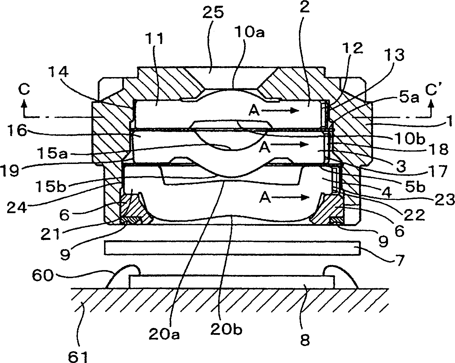
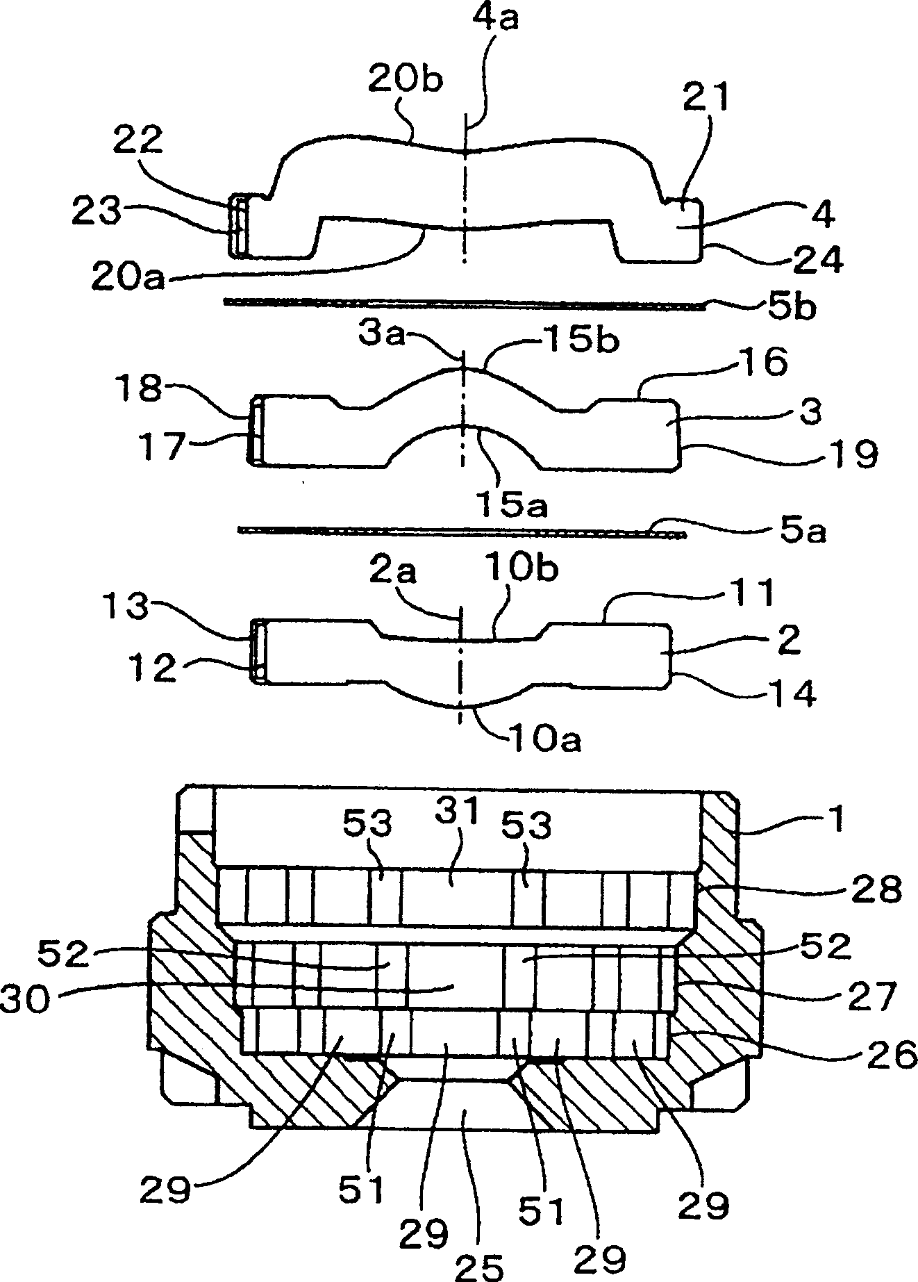
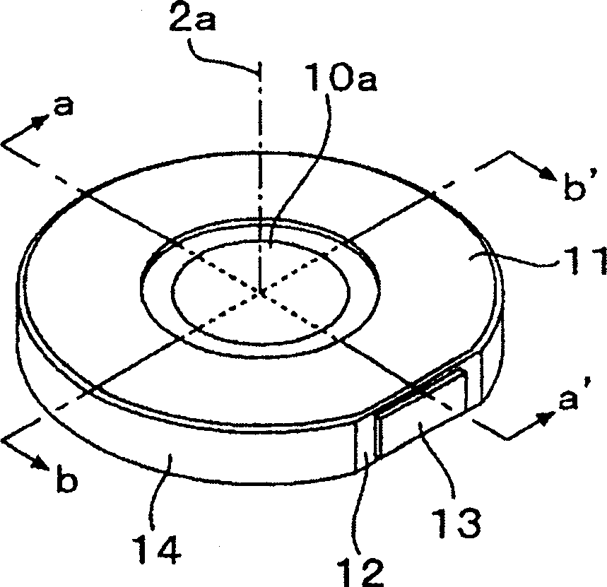
[0049] Hereinafter, embodiments of a lens device to which the present invention is applied will be described with reference to the drawings. figure 1 is a cross-sectional view of the lens device shown in Embodiment 1 of the present invention, figure 2 It is an exploded sectional view of main parts of the lens device of the present invention.

[0050] From figure 1 and figure 2 It can be seen that the basic composition of the lens device of this embodiment is: a black lens barrel 1 made of a mixture of black pigments such as polycarbonate resin, glass fiber, and carbon black with an outer diameter of 8mm, in the lens barrel 1 with a specified The first positive lens 2 with an outer diameter of 5.7 mm and a refractive power of 204 diopters, which is pressed and held at intervals and made of amorphous polyolefin resin, and the second positive lens 3 with an outer diameter of 5.9 mm and a refractive power of 38 diopters , a correction lens 4 with an outer diameter of 6.4mm an...


PUM


Abstract

In a lens device, plastic lenses having circular outer periphery are placed in a plastic lens-barrel having an octagonal or more complex polygonal inner surface in such a way that the outer peripheral surfaces of the lenses are press contacted to the inner surface of the polygonal shape. This lens device has press contact portions that are pressed by the lens outer peripheral surface and the lens-barrel inner surface in the vicinity and in both sides of gate traces where optical axis displacement is large so as to suppress the displacement of the gate trace by the press contact portions.

Description

technical field [0001] The present invention relates to a lens device in which a lens used in a camera or the like is inserted into a lens barrel and fixed. Background technique [0002] Cameras for digital cameras and mobile phones, etc., use a lens device in which one or more lenses are inserted into the lens barrel and fixed. Such a lens device is produced by inserting and fixing the lenses into the lens barrel so that the optical axes of the lens and the lens barrel and the optical axes between the plurality of lenses are coincident and aligned. [0003] On the other hand, in such a lens device, a plastic lens, a plastic lens barrel, etc. are used from the viewpoint of being easy to obtain an inexpensive product having an arbitrary shape. [0004] However, such a plastic lens or lens barrel is prone to expansion or contraction due to changes in temperature or humidity. When the lens is inserted into the lens barrel, fixed and assembled, even if the center is positioned,...

Claims


Application Information

Patent Timeline
Patent Type & Authority Applications(China)
IPC IPC(8): G02B7/02
CPCG02B13/0035G02B27/62G02B7/022G02B7/021
Inventor 平田弘之桥本昌俊
Owner MAXELL HLDG LTD
Why Eureka
Try Eureka