
Laser oscillation device

A technology of oscillation device and laser oscillator, which is applied in the direction of lasers, laser parts, laser welding equipment, etc., can solve the problems of processing position deviation, base plate deformation, dichroic mirror parallelism damage, etc., and achieve optical axis deviation Inhibition, small deformation effect

Active Publication Date: 2009-09-16
MITSUBISHI ELECTRIC CORP
View PDF8 Cites 0 Cited by
  • Summary
  • Abstract
  • Description
  • Claims
  • Application Information

AI Technical Summary

Problems solved by technology

For this reason, the heat of the laser oscillator deforms the base plate, the parallelism of each dichroic mirror is destroyed, and the optical axis of the laser beam deviates, causing a problem that the processing position deviates.

Method used


Image

  • Laser oscillation device
  • Laser oscillation device
  • Laser oscillation device

Examples


Embodiment Construction

[0018] Next, several embodiments of the present invention will be described with reference to the drawings.

[0019] Implementation form 1

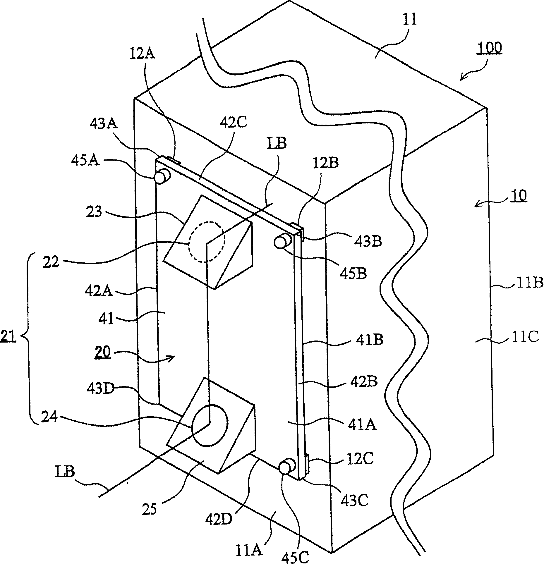
[0020] figure 1 It is a perspective view showing Embodiment 1 of the laser oscillator of the present invention. The laser oscillator 100 of the first embodiment is used in a laser processing machine, for example.

[0021] The laser oscillator 100 of Embodiment 1 has a laser oscillator 10 and an optical unit 20 . The laser oscillator 10 has a housing 11 in which laser light is generated. The box body 11 is formed in a rectangular parallelepiped box shape from metal such as a steel plate, and has a front wall 11A, a back wall 11B, and a peripheral wall 11C. The laser light generated by the laser oscillator 10 becomes a laser beam LB, which is extracted from the front wall 11A in a direction perpendicular thereto. Three mounts 12A, 12B, and 12C are formed on the front wall 11A.

[0022] The laser oscillator 10 is used, for example, by ...


PUM


Abstract

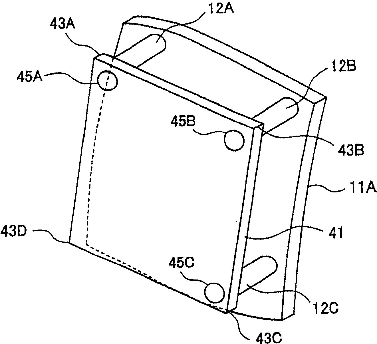
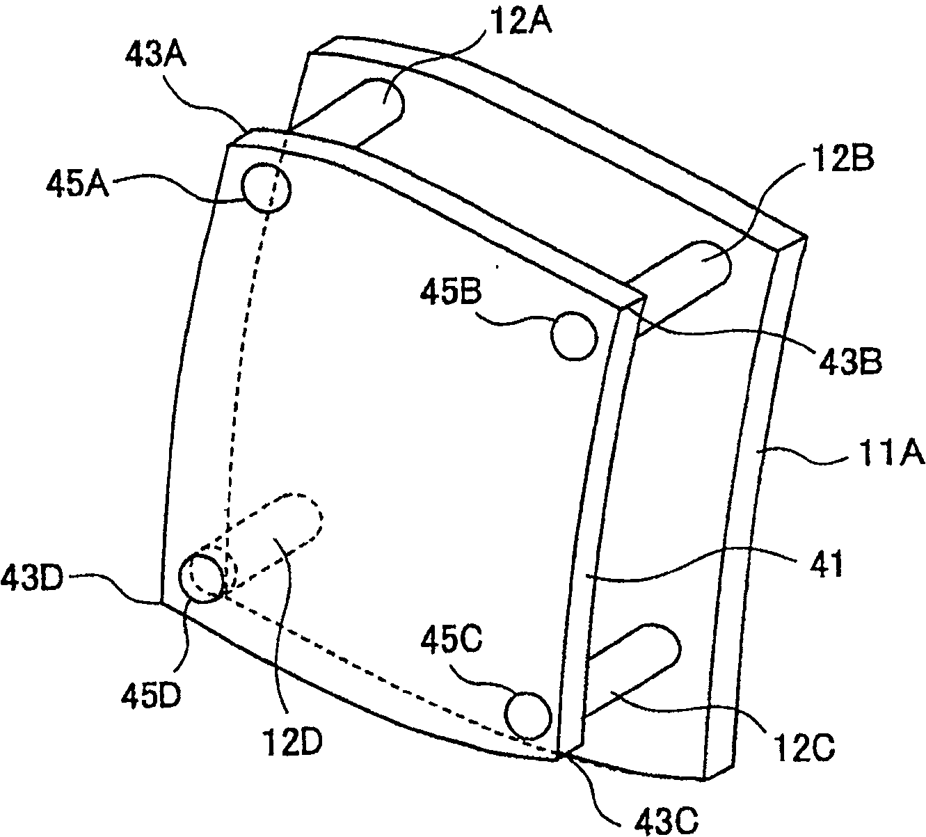
Laser oscillation device (100) comprises a common mirror support element (41) on which are arranged a first mirror (22) and a second mirror. The mirror support is mechanically connected to a housing (11) of a laser oscillator (10) using fixing elements (45A, 45B, 45C).

Description

technical field [0001] The present invention relates to a laser oscillator used in a laser processing machine and the like. Background technique [0002] In a laser processing machine that processes a workpiece with a laser beam, a laser oscillator including a laser oscillator and a plurality of mirrors is used. The laser oscillator has a housing, and laser light is generated inside the housing. The laser beam is transmitted as a laser beam to a processing section for processing a workpiece through a plurality of reflecting mirrors. [0003] The laser processing machine is disclosed in, for example, Japanese Patent Application Laid-Open No. 2002-316291 (Patent Document 1). figure 1 . In the laser oscillation device of the laser processing machine disclosed in this patent document 1, the linearly polarized laser beam output from the laser oscillator is circularly polarized by the first folding mirror, and the circularly polarized laser beam is circularly polarized by the s...

Claims


Application Information

Patent Timeline
Patent Type & Authority Patents(China)
IPC IPC(8): B23K26/04B23K26/06B23K26/42G02B27/00H01S3/02
CPCH01S3/0071G02B7/1815G02B7/182H01S3/02G02B17/02
Inventor 船冈幸治长谷川正彦玉谷基亮西田聪松本康成
Owner MITSUBISHI ELECTRIC CORP
Learn More