
Array lens manufacturing method, array lens, and array lens unit

A technology of array lens and manufacturing method, which is applied in the direction of lens, optical element, instrument, etc., and can solve problems such as the complexity of super-resolution processing

Inactive Publication Date: 2016-03-09
KONICA MINOLTA INC
View PDF8 Cites 2 Cited by
  • Summary
  • Abstract
  • Description
  • Claims
  • Application Information

AI Technical Summary

Problems solved by technology

However, if the pitch variation (expansion of the resin) caused by the temperature change is not the same, for example, even at the same temperature, the position between each lens changes when the temperature rises and when the temperature falls, and there is a possibility that the pitch variation will cause super Complicated processing such as resolution may cause adverse situations

Method used


Image

  • Array lens manufacturing method, array lens, and array lens unit
  • Array lens manufacturing method, array lens, and array lens unit
  • Array lens manufacturing method, array lens, and array lens unit

Examples


Embodiment Construction

[0020] Hereinafter, an array lens and the like according to one embodiment of the present invention will be described with reference to the drawings.

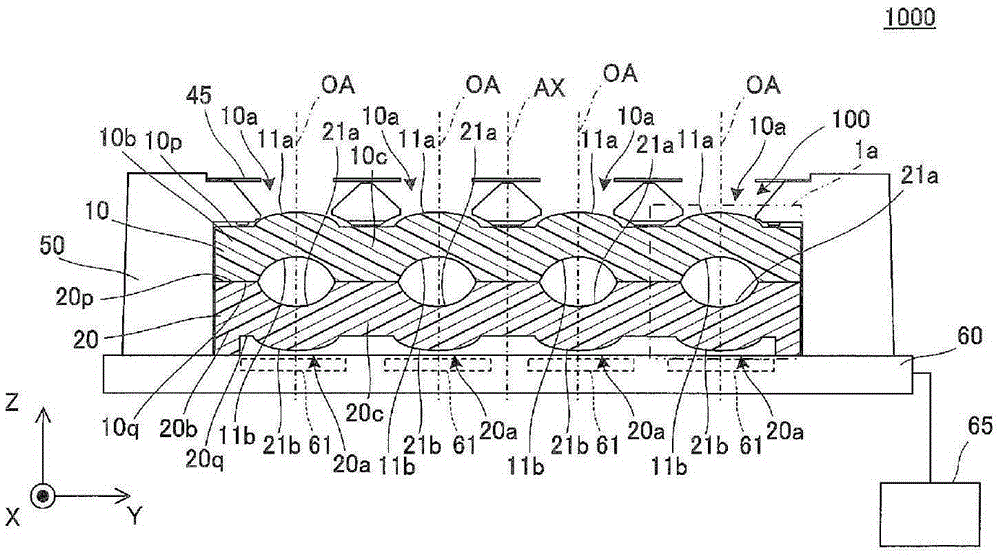
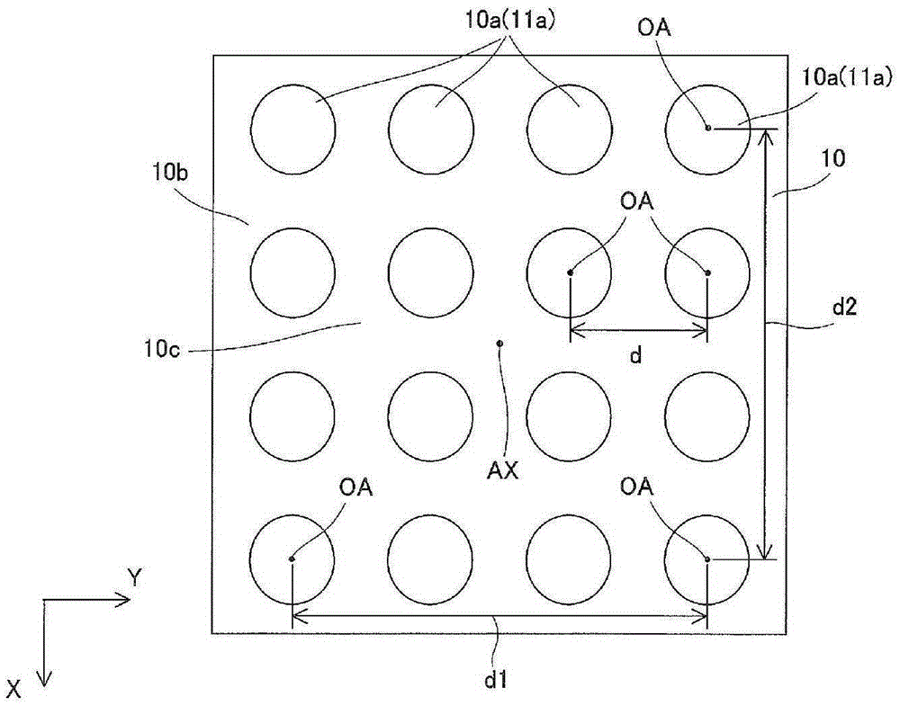
[0021] Such as Figure 1A As shown in and 1B , the stacked array lens unit 100 is assembled in the imaging device 1000 .

[0022] The illustrated stacked-type array lens unit 100 is a stacked body in which a plurality (specifically, two) array lenses 10 and 20 are stacked, and is used as a fly-eye optical system. The first and second array lenses 10 and 20 are square plate-shaped members extending parallel to the XY plane, and are stacked in the Z-axis direction perpendicular to the XY plane to be bonded to each other.

[0023] In addition, the imaging device 1000 includes, in addition to the array lens unit 100 described above, a sensor array 60 having a plurality of detection units (sensor elements) 61 provided corresponding to the respective synthetic lenses 1 a constituting the array lens unit 100 , and an image sensor arra...


PUM


Abstract

Provided is an array lens manufacturing method for which the variation in pitch between lens elements with changes in temperature is substantially the same for repeated temperature changes and hysteresis related to expansion and contraction has been substantially resolved. The array lens manufacturing method comprises: a forming process for integrally forming array lenses (10, 20), in which multiple lens elements (10a, 20a) arranged two dimensionally in the directions orthogonal to an optical axis (OA) and support sections (10b, 20b) connecting the multiple lens elements (10a, 20a) are formed, from resin; and a heat treatment process for performing, after the forming process, a heat treatment on the array lenses (10, 20) at a temperature of (Tg)-65DEG C to (Tg)-10DEG C for 24 to 168 hours when (Tg) is the glass transition temperature.

Description

technical field [0001] The present invention relates to a method of manufacturing a resin array lens, an array lens, and an array lens unit having a plurality of lens elements arranged in a direction perpendicular to an optical axis, and in particular to an imaging device or the like. Background technique [0002] In recent years, there has been a very high demand for thinner and lighter imaging optical systems. In response to this, the improvement of manufacturing accuracy corresponding to the shortening of the overall length based on the optical design and the accompanying increase in error sensitivity is sought. However, in order to meet the demand for further thinning and thinning, an image is obtained with an existing optical system and imaging element. This approach becomes insufficient. [0003] Therefore, in order to meet the demand for thinner and thinner, an optical system called a compound eye optical system that divides the area of ​​the imaging element, arrange...

Claims


Application Information

Patent Timeline
Patent Type & Authority Applications(China)
IPC IPC(8): B29C71/02G02B3/00
CPCB29C71/02B29C2071/022G02B13/0085G02B3/0031G02B3/005G02B3/0062B29D11/00432
Inventor 原明子
Owner KONICA MINOLTA INC
Learn More