Coating tool

A coating and tool technology, applied in the field of coating tools, can solve problems such as deterioration of workability, damage to edge parts and bags, and inclusions stuck into the side, etc., to achieve the prevention of deterioration of precision, excellent wear resistance, and suppression of internal stress Effect

Inactive Publication Date: 2006-08-02
MITSUBISHI MATERIALS CORP
View PDF3 Cites 3 Cited by
  • Summary
  • Abstract
  • Description
  • Claims
  • Application Information

AI Technical Summary

Problems solved by technology

[0008] However, in the above-mentioned coating tool, when the hardness of the content in the coating liquid is harder than that of the sides divided into slits, there will be scratches where the content is drawn in lines on the side surface, or the content will get stuck into the slit. side issues
Moreover, in the cleaning operation of the coating tool, there is also a hidden danger of damage to the side surface due to the inclusion, and the cleaning operation becomes difficult because the coating liquid enters such a damaged part.
[0009] In addition, there is a problem that fine lines are formed on the surface of the coating layer due to side damage
Conventionally, an edge member made of cemented carbide is attached to the front end portion of a head member made of stainless steel, thereby improving the wear resistance of the front end portion, but in

Method used


Image

  • Coating tool
  • Coating tool
  • Coating tool

Examples


Embodiment Construction

[0042] Hereinafter, embodiments of the present invention will be described with reference to the drawings.

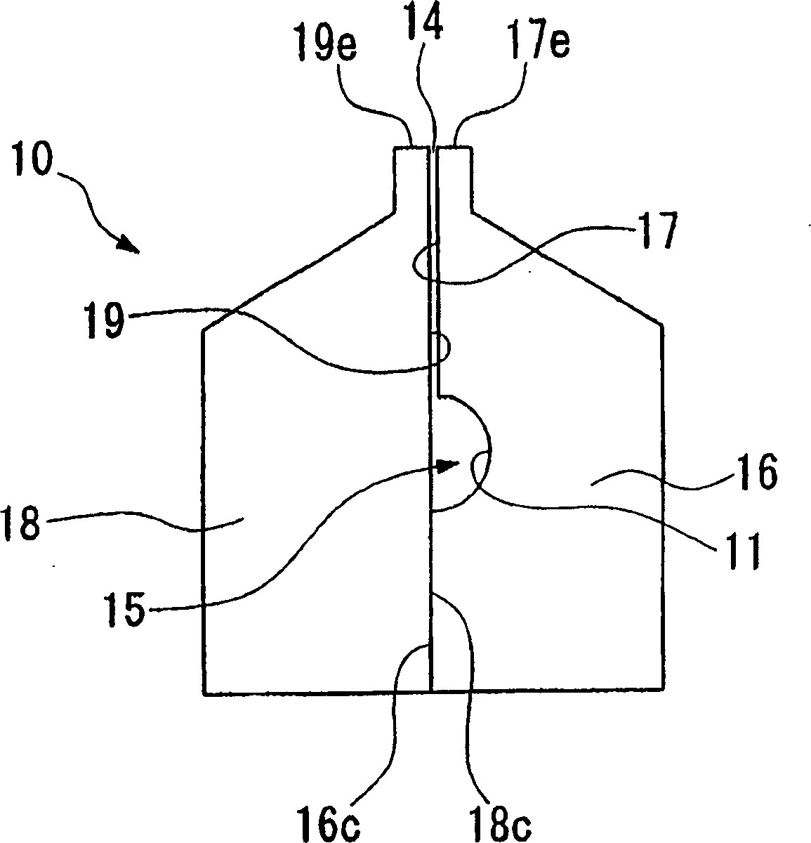
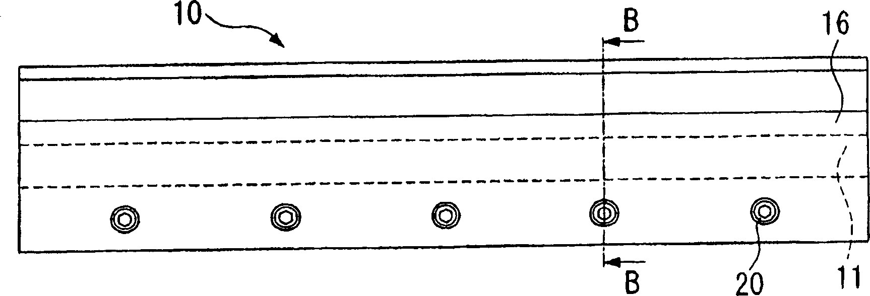
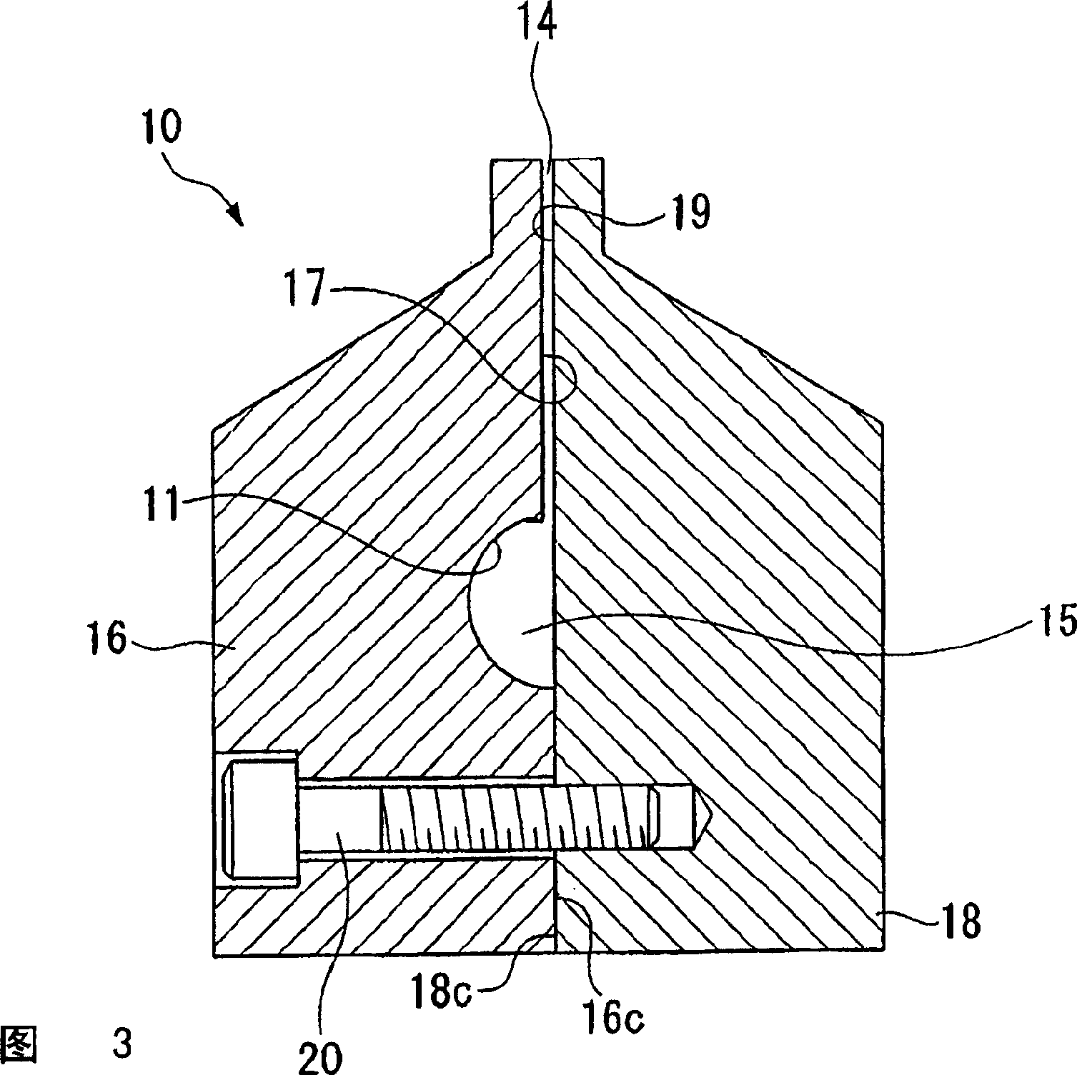
[0043] figure 1 It is the figure which observed the applicator head (tool main body) 10 of the 1st embodiment used for the applicator from the longitudinal direction, figure 2 yes figure 1 The right side view of Figure 3 is figure 2 The B-B section view.

[0044] The applicator head 10 is divided into slits 14 by arranging the opposing side surfaces (hereinafter referred to as slit surfaces) 17, 19 of a pair of head members 16, 18 with a certain gap. The mouth of the slit 14 is opened at the front end of the applicator head 10 . The head members 16, 18 protrude from the opening of the slit 14 to form front end surfaces 17e, 19e, and the application liquid is applied from the front end surfaces 17e, 19e.

[0045] The head member 16 constituting the applicator head 10 has grooves 11 formed in a semicircular shape in the longitudinal direction on the slit surface ...


PUM

PropertyMeasurementUnit
Densityaaaaaaaaaa

Abstract

The present invention provides a coating tool, comprising a coating head (10) having a plurality of head members (16) and (18), wherein a groove-like slot (14) opened to the tip of the coating head (10) is demarcated between the side faces (17) and (19) of the plurality of head members (16) and (18) opposed to each other, and coating solution is jetted from the tip of the coating head (10) through the slot (14). The coating tool is characterized in that the materials of the head members (16) and (18) is a titanium alloy, and that the slot faces (17) and (19) demarcating the slot are formed of a material harder than the titanium alloy.

Description

technical field [0001] The present invention relates to a coating tool for applying a coating liquid to the surface of a member to be coated, such as a thin plate-shaped member or a panel-shaped member. [0002] This application claims the priority of Japanese Patent Application No. 2003-190610, Japanese Patent Application No. 2003-201086, and Japanese Patent Application No. 2004-94556, and cites the contents of these patent applications. Background technique [0003] Conventionally, as a coating tool installed on a coating device for coating a coating liquid thinly and uniformly on the surface of a thin plate-shaped member to form a coating film layer, a coating liquid having a Applicator through the slit. As such coating tools, there are Figure 6 Shown is a coating tool provided with a coating head (tool body) 1. The coating head 1 is relative to a thin plate-shaped member S that travels along the direction of travel indicated by the arrow A in the figure, along which th...

Claims


Application Information

Patent Timeline
IPC IPC(8): B05C5/02
Inventor 三轮纪章挂桥典之安竹睦实金山利彦福田努
Owner MITSUBISHI MATERIALS CORP
Why Eureka
Try Eureka