
Heat exchange plate

A heat exchange plate and heat exchanger technology, applied in heat exchange equipment, heat transfer modification, heat exchanger type, etc., can solve problems such as performance deterioration, heat transfer performance deviation, and general versatility deterioration

Inactive Publication Date: 2006-08-09
XENESYS
View PDF3 Cites 17 Cited by
  • Summary
  • Abstract
  • Description
  • Claims
  • Application Information

AI Technical Summary

Problems solved by technology

When the intended use as a heat exchanger or the positional relationship between the plates of the heat exchanger causes changes in the flow conditions of the heat exchange fluid through the gaps between the plates, or when the fluid itself is replaced, the heat transfer performance may deviate from the optimum advantages, leading to severe performance degradation and general poor generality

Method used


Image

  • Heat exchange plate
  • Heat exchange plate
  • Heat exchange plate

Examples


Embodiment Construction

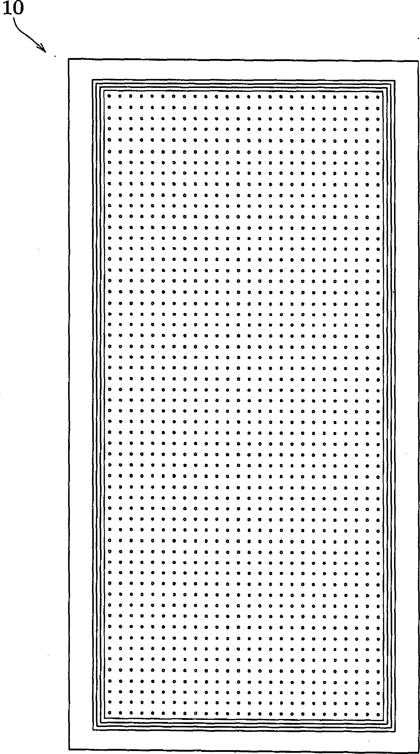
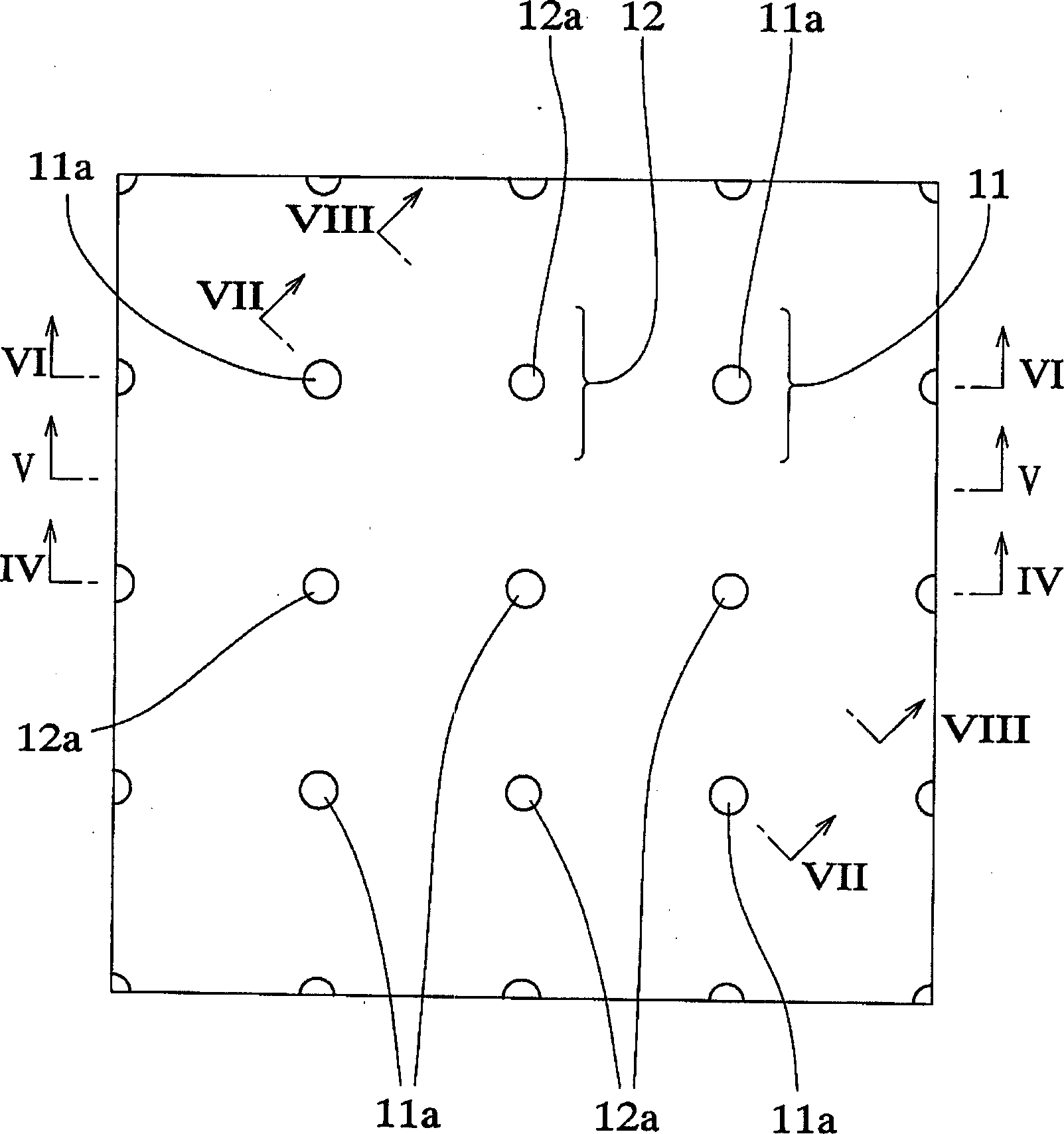
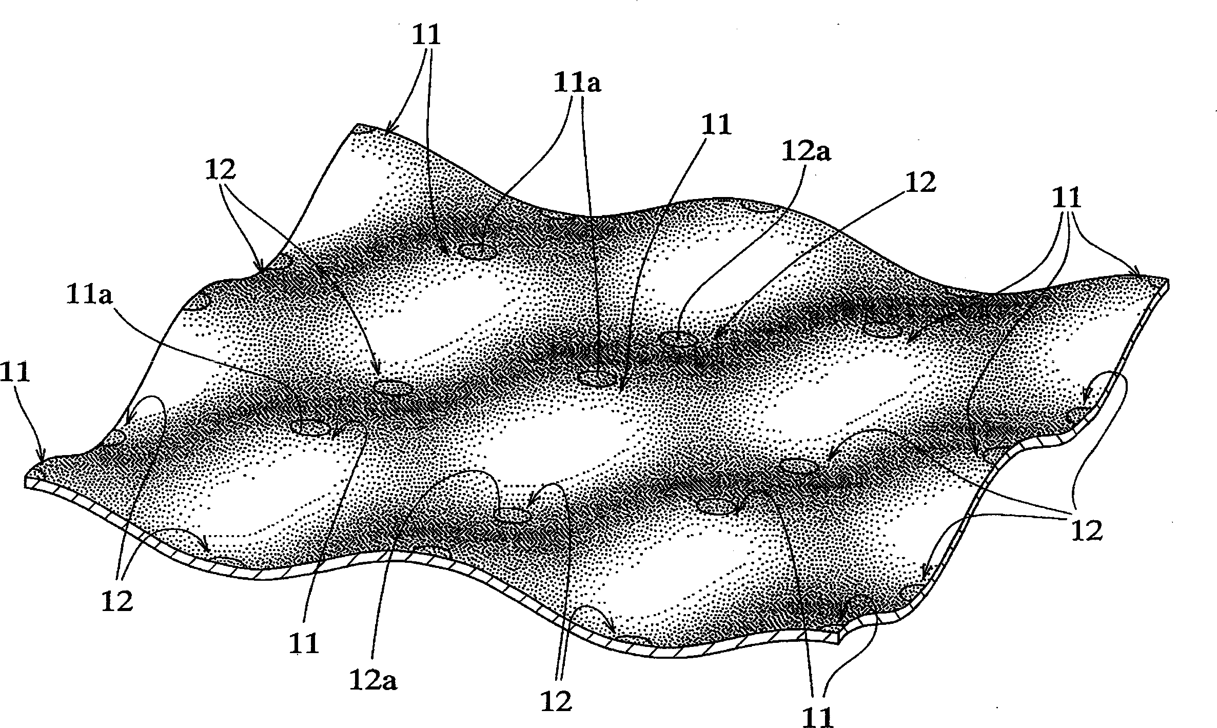
[0028] Now refer to Figure 1-Figure 10 An embodiment of the present invention will be described in detail. figure 1 is a schematic structural diagram of a heat exchange plate according to a first embodiment of the present invention, figure 2 for figure 1 An enlarged view of a portion of the heat exchange plate shown, image 3 for figure 1 A partially enlarged perspective view of the heat exchange plate shown, Figure 4 for along figure 2 A cross-sectional view taken on line IV-IV, Figure 5 for along figure 2 A cross-sectional view taken on line V-V, Figure 6 for along figure 2 The cross-sectional view taken on line VI-VI, Figure 7 for along figure 2 A cross-sectional view taken along line VII-VII, Figure 8 for along figure 2 A cross-sectional view taken on line VIII-VIII, Figure 9 and Figure 10 It is a structural view of the upper and lower gaps of the heat exchange plates according to the first embodiment of the present invention and in a state wher...


PUM


Abstract

A heat exchange plate has protrusions and recesses. The protrusion having a curved outer peripheral surface is surrounded by adjacent protrusions placed at regular intervals on a circle around the protrusion with the same central angle relative to the center of the protrusion. The recess having a curved inner peripheral surface that partially extends to the curved outer peripheral surface of the protrusion is placed in a predetermined arrangement that is deviated by the same pitch from the predetermined arrangement of the protrusions. The recesses provide on the other surface of the plate with the same configuration as the protrusions. The protrusions provide on the surface of the plate with the same configuration as the recesses, so as to provide on the opposite surfaces of the metallic plate with the same pattern of irregularity.

Description

technical field [0001] The present invention relates to a heat exchange plate, which is made of metal plate and used in combination with other heat exchange plates of the same structure, so that they are combined in parallel and integrated with each other to form a heat exchanger. In particular, the present invention relates to a heat exchange plate capable of forming a heat exchanger into an integrally combined state, in which heat exchange can be carried out correspondingly between heat exchange fluids under the same heat transfer conditions, At the same time, the heat exchanging fluid can be made to flow smoothly along the opposite surfaces of the heat exchanging plate, thereby improving the heat exchanging efficiency. Background technique [0002] If it is necessary to use a heat exchanger for heat transfer (ie, heat exchange) between a high-temperature fluid and a low-temperature fluid to increase the heat transfer coefficient to improve heat exchange efficiency, a plat...

Claims


Application Information

Patent Timeline
Patent Type & Authority Applications(China)
IPC IPC(8): F28D9/00F28F3/04F28F3/08F28F13/06
CPCF28F3/042F28D9/0031F28D9/0025F28F3/025F28F3/046
Inventor 松崎豊明渡边太郎
Owner XENESYS
Learn More