
Method of manufacturing lens sheet

A manufacturing method and lens technology, applied in the direction of lens, application, coating, etc., can solve problems such as glass substrate damage

Inactive Publication Date: 2006-08-09
ARISAWA MFG CO LTD
View PDF1 Cites 14 Cited by
  • Summary
  • Abstract
  • Description
  • Claims
  • Application Information

AI Technical Summary

Problems solved by technology

[0003] However, there is such a problem that when the lens is molded directly on the glass substrate using the existing technology, the glass substrate is hardly deflected when the mold is released, and the adhesion between the lens and the mold at the time of demoulding is much greater than the case of using a resin substrate. , resulting in unfavorable situations such as damage to the glass substrate during demoulding

Method used


Image

  • Method of manufacturing lens sheet
  • Method of manufacturing lens sheet
  • Method of manufacturing lens sheet

Examples


Embodiment Construction

[0023] Below, the present invention is illustrated by the embodiments of the invention, but the following embodiments are not intended to limit the scope of the claims of the present invention, and the combination of all features described in the embodiments is not necessarily necessary for the technical solution of the invention .

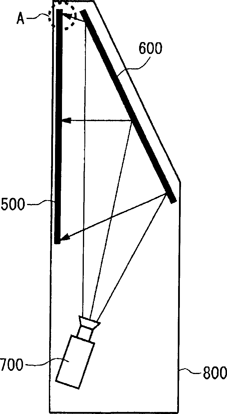
[0024] figure 1 The structure of a rear projection display 800 as an example of a lens is shown. The rear projection display 800 includes an optical engine (optical engine) 700 , a mirror (mirror) 600 and a screen (screen) 500 . The optical image output from the optical engine 700 is incident on the screen 500 after being reflected by the mirror 600 . The screen 500 diffuses the incident optical image and emits it toward the viewer, so as to realize an appropriate viewing area.

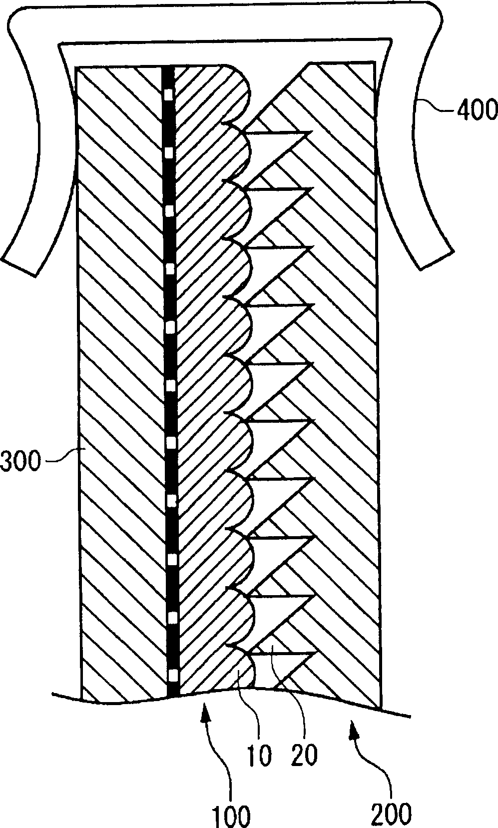
[0025] figure 2 express figure 1 The specific structure of part A of the screen 500. The screen 500 includes a Fresnel lens 200 , a lenticular lens 100 , and a fro...


PUM


Abstract

A method of manufacturing a lens sheet including: a mold making process in which the flexible mold used for molding the lens portion is made; a resin pouring process in which the resin for the lens portion is poured and filled in between the mold and the glass substrate; a resin curing process in which the resin for the lens portion is cured; and a mold releasing process in which the one edge of the mold is pulled up and bended the body thereof to be separated from the glass substrate completely.

Description

technical field [0001] The present invention relates to a manufacturing method of a lens having a plurality of concavities and convexities on one surface. Background technique [0002] For lenses such as Fresnel lenses and fly-eye lenses, if the overall rigidity of the sheet is insufficient, local contact with other parts will occur due to bending, and scratches or damages will occur on the surface of the mirror. Therefore, in order to increase the rigidity of the entire sheet, a technique of using a glass substrate as a base of the sheet has been studied (for example, refer to Japanese Patent Application Laid-Open No. 4-242703). [0003] However, there is such a problem that when the lens is molded directly on the glass substrate using the existing technology, the glass substrate is hardly deflected when the mold is released, and the adhesion between the lens and the mold at the time of demoulding is much greater than the case of using a resin substrate. , When the mold is...

Claims


Application Information

Patent Timeline
Patent Type & Authority Applications(China)
IPC IPC(8): G02B3/08B29D11/00
CPCB29C2035/0827B29C39/026B29D11/0073B29C35/0888B29D11/00269B29C33/444B29C33/40B29L2011/005B29C41/36B29C33/50
Inventor 下间裕之楚山诚浅野幸雄今井一成
Owner ARISAWA MFG CO LTD
Features
  • Generate Ideas
  • Intellectual Property
  • Life Sciences
  • Materials
  • Tech Scout
  • Unparalleled Data Quality
  • Higher Quality Content
  • 60% Fewer Hallucinations
Learn More