Electric motor winding with pole and power variable combination

A technology of motor windings and phase windings is applied in the field of improvement of motor winding connection methods, which can solve the problems that variable power motors cannot change poles at the same time, and pole changing motors cannot change output power, etc., so as to avoid large horse-drawn carts and improve efficiency. and the effect of power factor

Inactive Publication Date: 2006-08-16
HARBIN UNIV OF SCI & TECH +2
View PDF0 Cites 1 Cited by
  • Summary
  • Abstract
  • Description
  • Claims
  • Application Information

AI Technical Summary

Problems solved by technology

[0003] In order to solve the problem that the existing pole-changing motors cannot change the output power, and the variable-power motors cannot change the poles at the same time, a motor combining pole-changing and power-changing technologies is provided.

Method used


Image

  • Electric motor winding with pole and power variable combination
  • Electric motor winding with pole and power variable combination
  • Electric motor winding with pole and power variable combination

Examples


Embodiment Construction

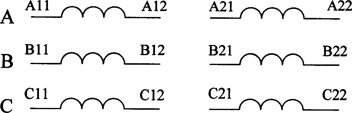
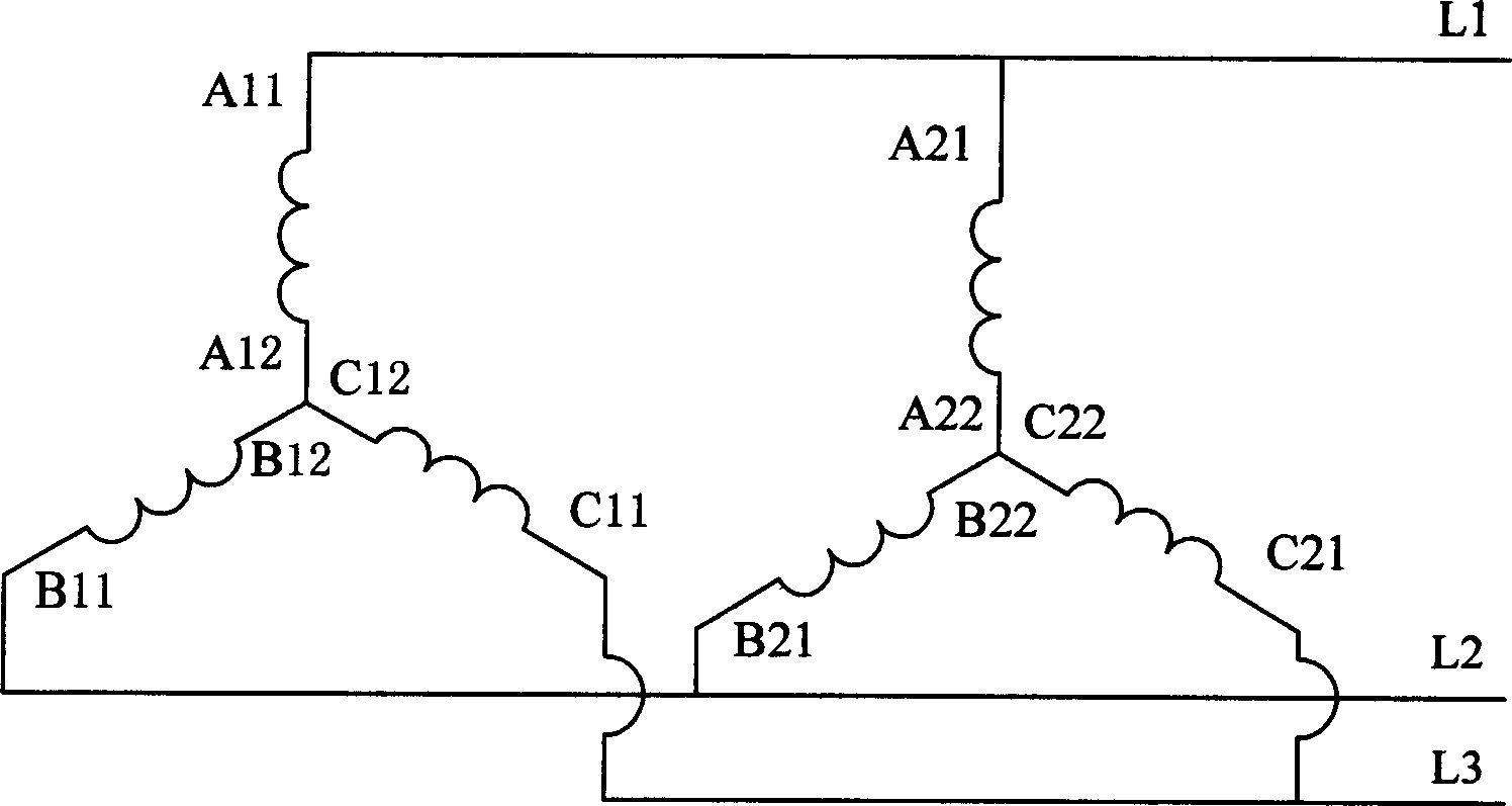
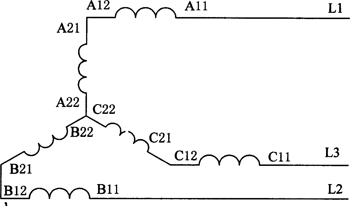
[0006] The motor winding in this specific embodiment includes A, B, and C three-phase windings, and each of the above-mentioned winding phases is divided into two subsections, each subsection has two lead-out ends at the beginning and the end, and each subsection contains 6 coils. The number of slots embedded in the motor winding is 36, and the pole-changing ratio is P / Q=4 / 6. The slot numbers of the A, B, and C three-phase windings of the motor winding are arranged in the following order:

[0007] Phase A winding first segment: 2 3 -10 -11 -12 19

[0008] Phase A winding second segment: 20 21 -28 -29 -30 1

[0009] Phase B winding first segment: -36 7 8 9 -16 -17

[0010] Phase B winding second segment: -18 25 26 27 -34 -35

[0011] Phase C winding first section: -4 -5 -6 13 14 15

[0012] Phase C winding second section: -22 -23 -24 31 32 33

[0013] (The number indicates the slot number, and the minus sign indicates reverse connection)

[0014] The first leading end of t...


PUM


Abstract

The invention solves the problem that is that the pole-changing motor can not change power of output and the power-changing motor can not change poles. The machine winding of the invention includes A, B, C three phases winding. Each phase winding is split into two segments, and each segment has two leading out end separately located in the front and tail. Each segment has m coils (m=1, 2, and the like). There are 12 leading out ends in total motor windings, and they get the following three structures through switching by relay: 1) a double star connection motor winding having P electrodes numbers at first power state; 2) a star connection motor winding having P electrode numbers at second power state; 3) a star connection motor winding having Q poles numbers at second power state.

Description

technical field [0001] The invention relates to the improvement of the wiring method of motor windings. Background technique [0002] At present, there are many variable power motors, most of which achieve the purpose of variable power by controlling the connection mode of the stator windings through relays; there are also many variable pole motors, for example, screw pump pumping units used in oil fields, which can obtain different speeds. However, the screw pump pumping unit cannot change the output power, and cannot change the output power according to the change of the oil layer in the oil field. When the output power is small, that is, under light load conditions, a large horse-drawn cart will be formed, resulting in a decrease in the efficiency of the motor. It is necessary to change the winding connection mode of the motor to match the output power, so as to obtain higher efficiency and power factor, and achieve the purpose of saving energy. Therefore, a new research ...

Claims


Application Information

Patent Timeline
IPC IPC(8): H02K3/28
Inventor 李伟力陈文彪沈稼丰黄士鹏夏德媛周封宋德风
Owner HARBIN UNIV OF SCI & TECH
Why Eureka
Try Eureka