Punched hole processing method of flexible printed circuit lining
A technology of a flexible printed circuit and a processing method, which is applied in the field of punching processing, can solve the problems of drop in suction pressure, poor operation efficiency, and difficulty in realization, and achieves the effect of improving operation efficiency and eliminating unfavorable situations.
- Summary
- Abstract
- Description
- Claims
- Application Information
AI Technical Summary
Problems solved by technology
Method used
Image
Examples
Embodiment 1
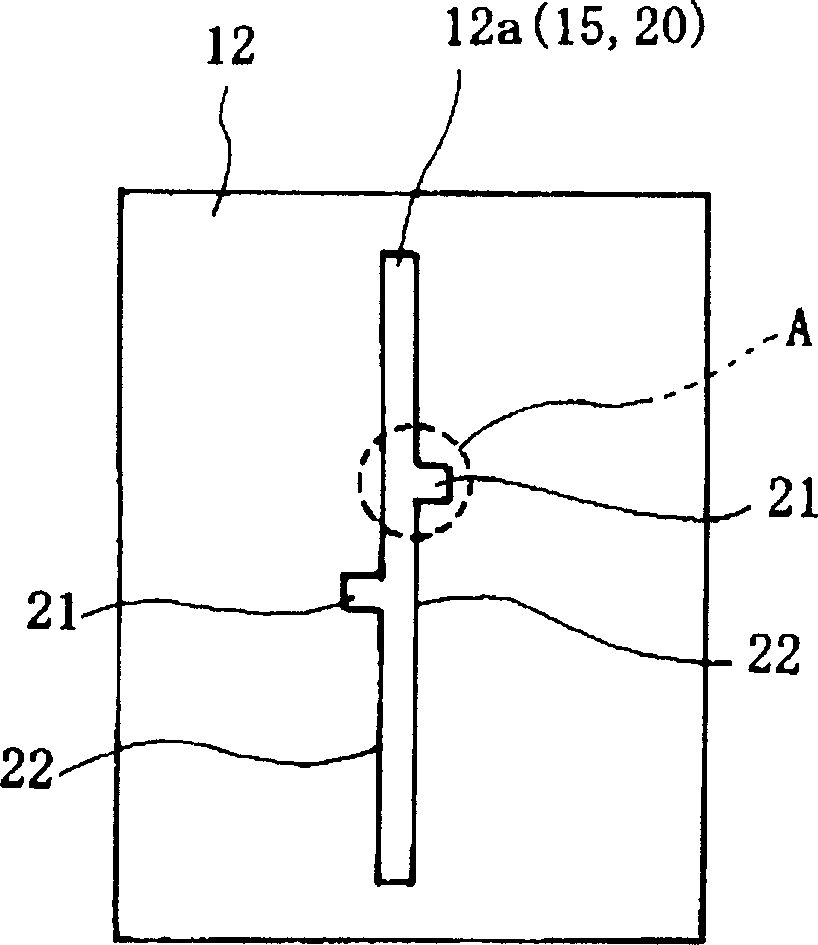
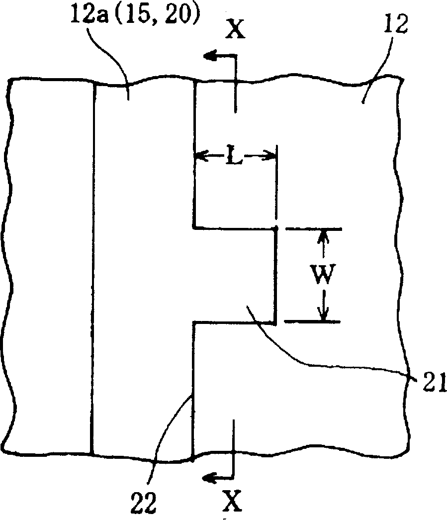
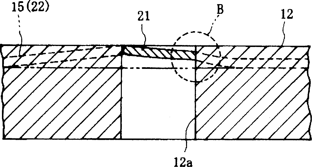
[0046] figure 1 ~ FIG. 4 shows an example of the punching process in which the elongated opening is formed by punching in the flexible printed circuit substrate, figure 1 A top view of the bottom mold 12 into which the punching waste 15 formed for punching the elongated opening of the flexible printed circuit substrate enters, figure 2 for the reason figure 1 An enlarged view of the portion surrounded by the dashed line A shown, image 3 to indicate along figure 2 The longitudinal sectional view of the movement of the blanking waste in the bottom die at the X-X line in FIG. 4 is an explanatory plan view showing various shapes of the convex punching part.
[0047] picture Figure 1 ~ Figure 3 As shown, in the punch hole 12 a of the bottom die 12 , one or more convex punching portions 21 are continuously provided at a position near the longitudinal middle portion of the linear elongated opening 20 . The convex punching part 21 can be arranged on any side within 5 mm fr...
Embodiment 2
[0053] Figure 5 ~ FIG. 7 shows another example of punching process for forming elongated openings in flexible printed circuit substrates by punching, Figure 5 A top view of the bottom mold 12 into which the punching waste 15 formed for punching the elongated opening of the flexible printed circuit substrate enters, Figure 6 for the reason Figure 5 FIG. 7 is an enlarged view of the portion surrounded by the dotted line C shown, and FIG. 7 is an explanatory plan view showing the corresponding shape of the concave non-punched portion.
[0054] picture Figure 5 and Figure 6 As shown, in the punch hole 12a of the bottom mold 12 of the second embodiment, a linear elongated opening 30 having a width greater than that of the first embodiment is formed, and the longitudinal middle portion of the elongated opening 30 is In the vicinity, one or more concave non-punched portions 31 are continuously provided toward the inner side. The concave non-punching portion 31 can be provi...
Embodiment 3
[0060] Figure 8 shows an example of the punching process of forming curved elongated openings by punching on the flexible printed circuit substrate, as shown in Figure 8 (1), the punch hole 12a of the bottom mold 12 is gentle One or more convex punching parts 41 are continuously provided in the vicinity of the longitudinal middle part of the elongated opening 40 of the curved punch hole 12a in a curved shape.
[0061] Preferably, the convex punching portion 41 has a rectangular shape in die processing, but it can also be in other shapes such as trapezoid, triangle, sickle shape, semicircle, etc. as in the case of the first embodiment. In addition, the length of the punched portion 41 and the outer corner of the opposite longitudinal side edge portion 42 are also the same as in the case of the first embodiment. As shown in the figure, the convex punching portion 41 is formed outside the curved elongated opening 40 , thereby further effectively suppressing the winding up of the ...
PUM
 Abstract
Description
Claims
Application Information
 - R&D
- Intellectual Property
- Life Sciences
- Materials
- Tech Scout
- Unparalleled Data Quality
- Higher Quality Content
- 60% Fewer Hallucinations
Browse by: Latest US Patents, China's latest patents, Technical Efficacy Thesaurus, Application Domain, Technology Topic, Popular Technical Reports.
© 2025 PatSnap. All rights reserved.Legal|Privacy policy|Modern Slavery Act Transparency Statement|Sitemap|About US| Contact US: help@patsnap.com


