
Punched hole processing method of flexible printed circuit lining

A technology of a flexible printed circuit and a processing method, applied in the field of punching processing, can solve the problems of drop in suction pressure, poor operation efficiency, and difficulty in realization, and achieve the effect of improving operation efficiency and eliminating unfavorable situations.

Inactive Publication Date: 2010-08-18
NIPPON MEKTRON LTD
View PDF2 Cites 0 Cited by
  • Summary
  • Abstract
  • Description
  • Claims
  • Application Information

AI Technical Summary

Problems solved by technology

[0011] Thus, there is a problem that when installing a new flexible printed circuit substrate 14, it must be confirmed each time that there is no blanking waste 15 on the surface of the bottom mold 12, and when there is a blanking waste 15, it must be checked by blowing. After the blanking waste 15 is removed by air and brush, the next flexible printed circuit substrate 14 is installed, and the work efficiency is poor
[0012] It is also considered that the bottom of the bottom mold 12 has a sealed structure in such a way that the blanking waste 15 does not bulge on the surface of the bottom mold 12, and the method of discharging the blanking waste 15 by air suction is also considered. However, when there are multiple pairs of flexible printed circuits When the part where the substrate 14 is punched is sucked by the same system, there is a disadvantage that the suction pressure drops at the moment the punching waste 15 is discharged at any one of the multiple parts, and the suction and discharge operation cannot be continuously performed.
Suction mechanisms can be installed on all the parts where the punching process is performed, but the mold structure is complicated and it is difficult to realize

Method used


Image

  • Punched hole processing method of flexible printed circuit lining
  • Punched hole processing method of flexible printed circuit lining
  • Punched hole processing method of flexible printed circuit lining

Examples


Embodiment 1

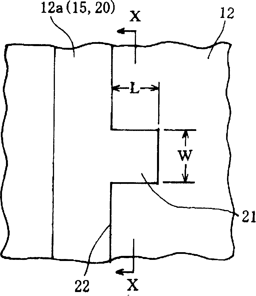
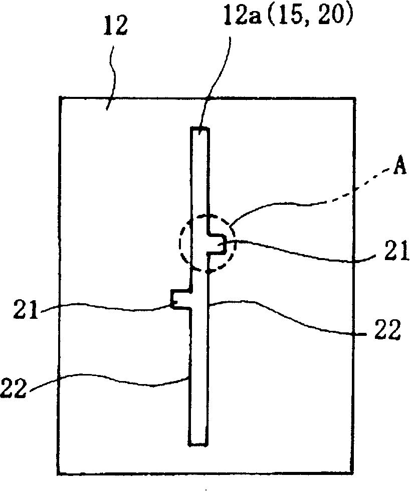
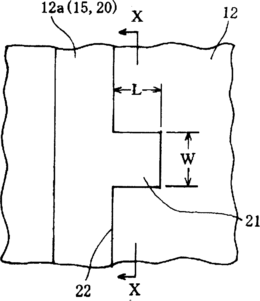
[0046] Figures 1 to 4 show an example of the punching process for forming the elongated opening in the flexible printed circuit substrate by punching. A top view of the bottom mold 12 where blanking waste 15 enters. FIG. 2 is an enlarged view of the part surrounded by the dotted line A shown in FIG. 1, and FIG. A longitudinal sectional view of the movement, and FIG. 4 is an explanatory plan view showing various shapes of the convex punching portion.

[0047] As shown in FIGS. 1 to 3 , in the punch hole 12 a of the bottom die 12 , one or more convex punching portions are continuously provided near the longitudinal middle portion of the linear elongated opening 20 . twenty one. The convex punching part 21 can be arranged on any side within 5 mm from the longitudinal middle part of the above-mentioned elongated opening part 20. The two sides near the middle part are arranged so that their positions are slightly shifted.

[0048] In this embodiment, the above-mentioned convex p...

Embodiment 2

[0053] Figures 5 to 7 show another example of the punching process for forming the elongated openings in the flexible printed circuit substrate by punching, and Figure 5 is formed by punching the elongated openings of the flexible printed circuit substrate. Figure 6 is an enlarged view of the part surrounded by the dotted line C shown in Figure 5, and Figure 7 is an explanatory top view showing the corresponding shape of the concave non-punching part.

[0054] As shown in FIGS. 5 and 6, in the punch hole 12a of the bottom mold 12 of the second embodiment, a linear elongated opening 30 having a width greater than that of the first embodiment is formed. One or more concave non-punched portions 31 are continuously provided toward the inner side near the longitudinal middle portion of the portion 30 . The concave non-punching portion 31 can be provided on any side within 5 mm from the longitudinal middle portion of the above-mentioned elongated opening 30. However, if there is no ...

Embodiment 3

[0060] Figure 8 shows an example of the punching process of forming curved elongated openings by punching on the flexible printed circuit substrate, as shown in Figure 8 (1), the punch hole 12a of the bottom mold 12 is gentle One or more convex punching parts 41 are continuously provided in the vicinity of the longitudinal middle part of the elongated opening 40 of the curved punch hole 12a in a curved shape.

[0061] Preferably, the convex punching portion 41 has a rectangular shape in die processing, but it can also be in other shapes such as trapezoid, triangle, sickle shape, semicircle, etc. as in the case of the first embodiment. In addition, the length of the punched portion 41 and the outer corner of the opposite longitudinal side edge portion 42 are also the same as in the case of the first embodiment. As shown in the figure, the convex punching portion 41 is formed outside the curved elongated opening 40 , thereby further effectively suppressing the winding up of the ...


PUM


Abstract

To sequentially discharge punch chad from a tapered part of a lower die downward without being turned over on the surface of a lower die even if the metal mold having a short stroke wherein a punch does not insert through from a punch hole of the lower die to the position projecting to the tapered part in the punching machining method to punch and form a slender opening part on a flexible printedcircuit board. The projecting punching part 21 is continuously provided at a position in the vicinity of an approximate central part of the longitudinal direction side edge part 22 of the linear slender opening part 20 in the punch hole 12a of the lower die 12 of the punch. Since the part of length L orthogonally projecting from the side edge part 22 of the slender opening part generates the friction force between the lower die 12 and the punch chad 15, the projecting shape punching part 21 can suppress the punch chad 15 from being turned over.

Description

technical field [0001] The present invention relates to a punching method for flexible printed circuit substrates used in electronic equipment, and particularly relates to punching for forming elongated openings such as slits and dividing slits by punching using a punch for punching processing method. Background technique [0002] As a method of forming non-through holes, openings for receiving electronic components, and the like in a flexible flexible printed circuit board, punching using a punch for punching is widely performed. Usually, a necessary conductor circuit is formed on an insulating substrate with copper foil or the like, covered with a cover layer, a solder resist, etc., and then punched. [0003] In the punching process in the past, it is known that there is a method of inserting a flexible printed circuit substrate between the top mold and the bottom mold, and punching holes while pressing the flexible printed circuit substrate through the pressing plate of ...

Claims


Application Information

Patent Timeline
Patent Type & Authority Patents(China)
IPC IPC(8): H05K3/00B26F1/14
Inventor 堀切薰一石和博
Owner NIPPON MEKTRON LTD
Learn More