Testing apparatus and testing method for an electronic interlocking system

A kind of interlocking and electronic technology, which is applied to the interlocking device between the switch and the signal, the interlocking device in the station, the control system of the transportation center, etc., which can solve the problems of shortening the experiment time and costing the wiring operation.

Inactive Publication Date: 2006-08-30
HITACHI LTD
View PDF2 Cites 6 Cited by
  • Summary
  • Abstract
  • Description
  • Claims
  • Application Information

AI Technical Summary

Problems solved by technology

In the case of inserting a switch, there is a problem that wiring work costs
In addition, in the case of changing the cables for each experiment, it is necessary to switch the connection from the simulation mechanism to the field machine before the experiment, and to switch the connection from the field machine back to the simulation mechanism after the experiment, and there is a replacement cost. The problem
In addition, since the connection confirmation is required after the connection is restored, there is a problem that the experiment time is shortened.

Method used


Image

  • Testing apparatus and testing method for an electronic interlocking system
  • Testing apparatus and testing method for an electronic interlocking system
  • Testing apparatus and testing method for an electronic interlocking system

Examples


Embodiment Construction

[0021] The best mode for carrying out the present invention will be described.

[0022] Hereinafter, embodiments of the electronic interlocking system, experimental equipment, and experimental method of the present invention will be described with reference to the drawings.

[0023] (Example)

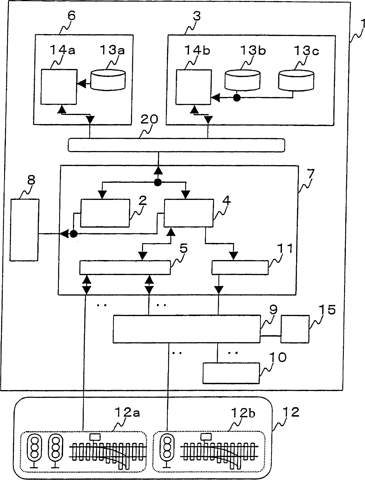
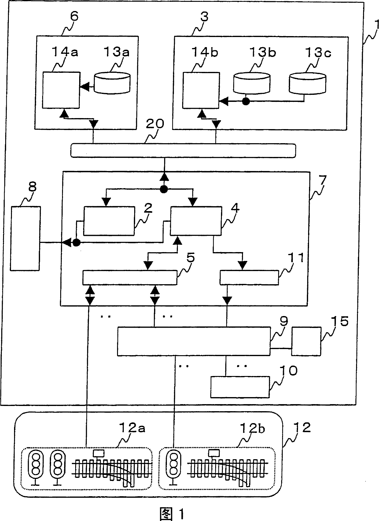
[0024] Examples will be described. FIG. 1 shows an apparatus configuration at the time of a switching experiment of an electronic interlock system as one embodiment of the present invention. The chain logic part 6 is connected to the field control terminal 7 via LAN20. Moreover, the experiment system interlocking logic part 3 used for an experiment is also connected to the said LAN20. The interlock logic unit 6 and the experiment system interlock logic unit 3 generate control commands for controlling field devices 12 such as switches and signal lamps, and output them to the field control terminal 7 via the LAN 20 .

[0025] Among the above-mentioned field devices 12, there are a fie...


PUM


Abstract

This electronic interlocking system comprises an interlocking logic part 6 creating control commands of a field apparatus 12, a field control terminal 7 outputting controls to the field apparatus 12, and simulation means 10 simulating a function of the railway signal field apparatus 12 at the time of test. The system is equipped with a test system interlocking logic part 3 connected with the field control terminal 7 and having a follow mode for performing control not to avoid the action of the interlocking logic part 6. The interlocking logic part 6 and the test system interlocking logic part 3 output independent control commands relative to the railway signal field apparatus 12 along with output existence/absence information to the field control terminal 7. The field control terminal 7 outputs control commands of the interlocking logic part 6 when the interlocking logic part 6 outputs the control commands outputted to the field apparatus 12 and the test system interlocking logic part 3 is in a follow mode or does not output.

Description

technical field [0001] The present invention relates to an electronic interlocking system for railway signal control, in particular to the electronic interlocking system and its experimental method when modifying already designed field machines and extending the functions of the electronic interlocking system. Background technique [0002] Hereinafter, the conventional method for modifying the function of the electronic chain system will be described. When establishing a new electronic interlocking system or comprehensively updating equipment, the newly established electronic interlocking system is generally set up adjacent to the original equipment, and the newly established electronic interlocking system is connected to the original on-site simulation mechanism to confirm the function Afterwards, when the original equipment is not working, the newly established electronic interlocking system is connected with the original equipment for experimentation. [0003] In additio...

Claims


Application Information

Patent Timeline
Patent Type & Authority Applications(China)
IPC IPC(8): B61L19/06
CPCB61L27/0055B61L21/04B61L27/60E04G9/06
Inventor 细川润一网谷宪晴小熊贤司
Owner HITACHI LTD
Why Eureka
Try Eureka