Wind wheel blade

A windmill and wing chord technology, applied in the field of windmill wings, can solve the problems such as windmill wing rotation influence, ease of assembly and disassembly, etc. maintenance is not enough, time-consuming, etc., to achieve easy road selection and time-consuming handling operations Effect

Inactive Publication Date: 2011-03-23
MITSUBISHI HEAVY IND LTD
View PDF3 Cites 12 Cited by
  • Summary
  • Abstract
  • Description
  • Claims
  • Application Information

AI Technical Summary

Problems solved by technology

If the amount of garbage, sand, etc. is large, it will affect the rotation of the wind turbine blades, reduce the power generation efficiency, and become the main cause of damage
However, it is difficult and time-consuming to remove these garbage, silt, etc.
[0012] In addition, although various efforts have been made on the technologies shown in Patent Document 1 to Patent Document 3, they cannot be said to be sufficient in terms of maintainability such as ease of assembly and disassembly, and further improvement is required.

Method used


Image

  • Wind wheel blade
  • Wind wheel blade
  • Wind wheel blade

Examples


no. 1 approach

[0063] based on Figure 1 ~ Figure 3 The wind power generator 1 according to the first embodiment of the present invention will be described.

[0064] figure 1 It is a side view showing the overall schematic configuration of the wind power generator 1 .

[0065] like figure 1 As shown, the wind power generation device 1 has: a pillar 3 erected on the base 11; a nacelle 5 arranged on the upper end of the pillar 3; a rotor head 7 that can rotate around a substantially horizontal axis and is arranged on the nacelle 5; The rotation axis of the rotor head 7 is a plurality of, for example, three windmill blades 9 installed radially.

[0066] The force of the wind blowing from the direction of the rotation axis of the rotor head 7 onto the windmill blade 9 is converted into power to rotate the rotor head 7 around the rotation axis.

[0067] An anemometer 13 for measuring peripheral wind speed values, an anemometer 15 for measuring wind direction, and a lightning rod (not shown) a...

no. 2 approach

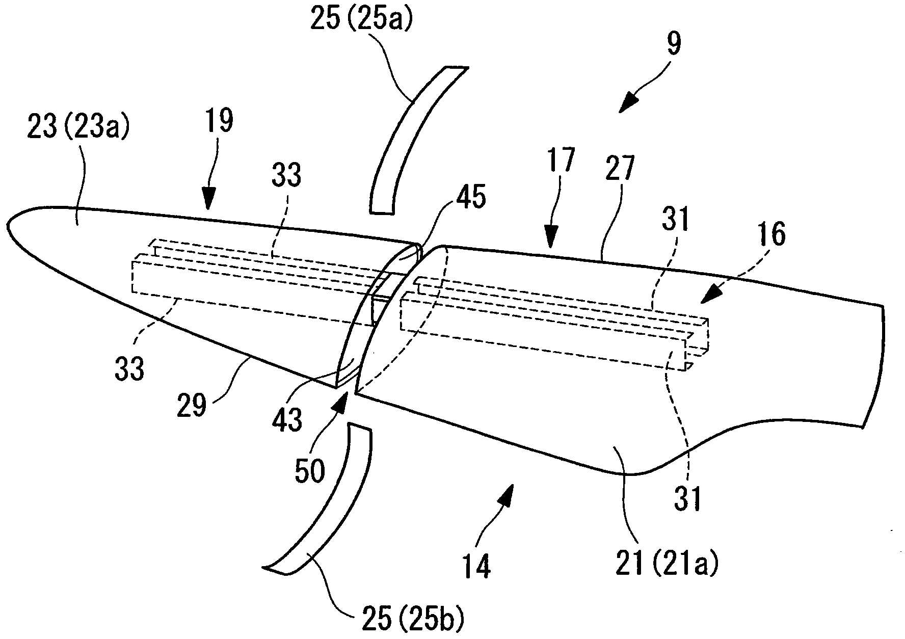
[0116] Below, combine Figure 4 ~ Figure 6 A wind turbine blade 9 according to a second embodiment of the present invention will be described.

[0117] The difference between this embodiment and the first embodiment lies in the configuration of the main beam 16 and the joint structure, so here, the difference will be mainly described, and the repeated description of the same parts as the first embodiment will be omitted. Moreover, the same code|symbol is attached|subjected to the same component as 1st Embodiment.

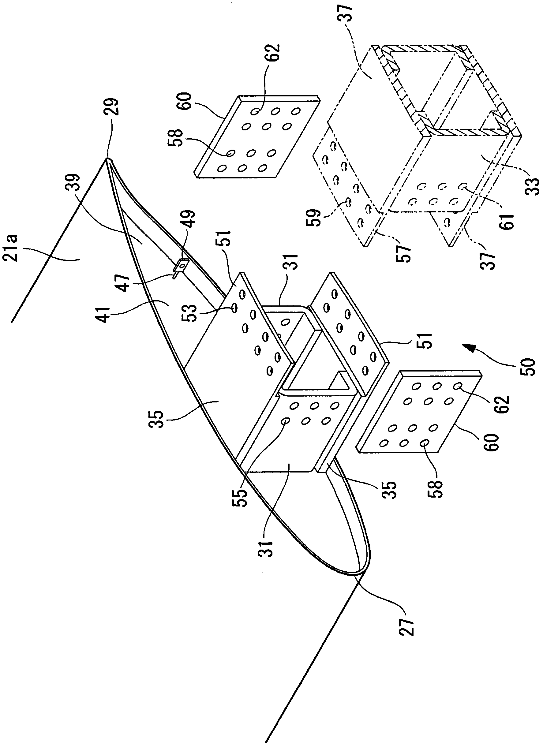
[0118] In this embodiment, there is one main beam 16 which is a hollow member having a rectangular cross-sectional shape. The joint portion 50 is provided with a joint member 63 for joining the root-side main spar 31 and the wing-top side main spar 33 . The coupling member 63 has a substantially hollow rectangular parallelepiped shape, and is configured to be able to insert the root-side main spar 31 and the wing-top side main spar 33 into the hollow portion.

[...

no. 3 approach

[0129] Below, combine Figure 9 as well as Figure 10 A wind turbine blade 9 according to a third embodiment of the present invention will be described.

[0130] The difference between the present embodiment and the first embodiment lies in the configuration of the main beam 16 and the joint structure. Therefore, the different parts will be mainly described here, and the repeated description of the parts that are the same as those in the first embodiment will be omitted. Moreover, the same code|symbol is attached|subjected to the same component as 1st Embodiment.

[0131] In this embodiment, there are two wing root side main girders 31 , and the two wing root side main girders 31 are integrated at the end of the wing top side and have a rectangular cross section. There are two main beams 33 on the top side of the wing, and the two main beams 33 on the top side of the wing are integrated at the end of the wing root side and have a rectangular cross section.

[0132] The join...


PUM


Abstract

A wind wheel blade, wherein the wind wheel blade is efficiently mounted in a satisfactory state by minimizing the entry of foreign matter into the blade during transportation. A wind wheel blade (9) is provided with a long hollow outer skin (14), a main beam (16) inserted in the longitudinal direction in the outer skin (14) and reinforcing the outer skin (14) from the inside thereof. The main beam (16) is divided into a blade base main beam (31) and a blade top main beam (33) which are arranged next to each other in the longitudinal direction. The blade base main beam (31) and the blade top main beam (33) have a joint section (50) at which the main beams (31, 33) are joined together. The outer skin (14) is divided into a joint section outer skin (25) located at a position corresponding to the joint section (50), a blade base outer skin (21), and a blade top outer skin (23), and opening portions (43) formed in the blade base outer skin (21) and the blade top outer skin (23) are sealed by closing plates (45).

Description

technical field [0001] The invention relates to a windmill wing. Background technique [0002] In recent years, wind power generators tend to be enlarged in order to improve the power generation efficiency and increase the power generation amount. Along with the increase in size of wind power generators, windmill blades also need to be increased in size, for example, the blade length should be 40 meters or more. [0003] If it is enlarged in this way, not only is it difficult to manufacture it integrally, but it is also difficult to carry it along with difficulties such as transporting it on a road, and various difficulties arise. [0004] In order to solve this difficulty, as shown in Patent Document 1 to Patent Document 3, it has been proposed to divide the wind turbine blade in the longitudinal direction. [0005] The technique proposed in Patent Document 1 is a divided structure in which sufficient strength is ensured only by the casing. The technique proposed in Pate...

Claims


Application Information

Patent Timeline
Patent Type & Authority Applications(China)
IPC IPC(8): F03D11/00F03D1/06
CPCF03D1/0675Y02E10/721F05B2260/63F03D1/0683Y02E10/722F05B2240/302Y02E10/72F05B2230/60
Inventor 川节望江崎浩司黑岩隆夫堀进一
Owner MITSUBISHI HEAVY IND LTD
Why Eureka
Try Eureka