
Towing pin

A technology of traction bolts and cylinders, which is applied to ship parts, ships, towing/push equipment, etc., and can solve problems such as damage and wear

Active Publication Date: 2006-08-30
康士伯航海公司
View PDF0 Cites 3 Cited by
  • Summary
  • Abstract
  • Description
  • Claims
  • Application Information

AI Technical Summary

Problems solved by technology

In addition, tie-downs, especially steel wires and fiber-steel cables, abrade the edges of the grooves, causing significant damage

Method used

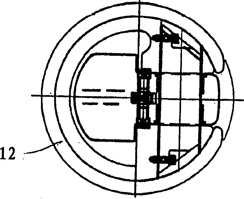

Image

  • Towing pin
  • Towing pin
  • Towing pin

Examples


Embodiment Construction

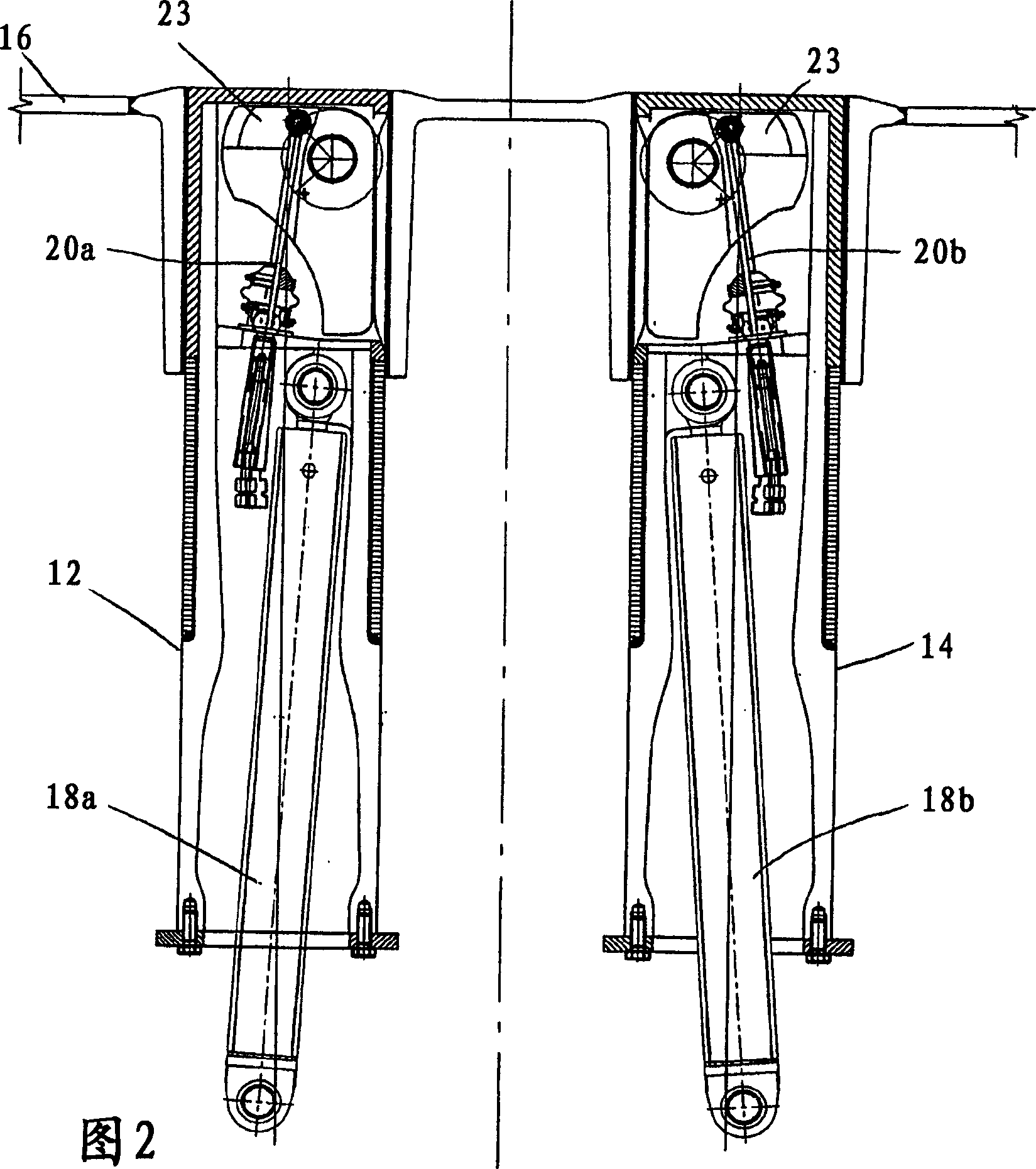
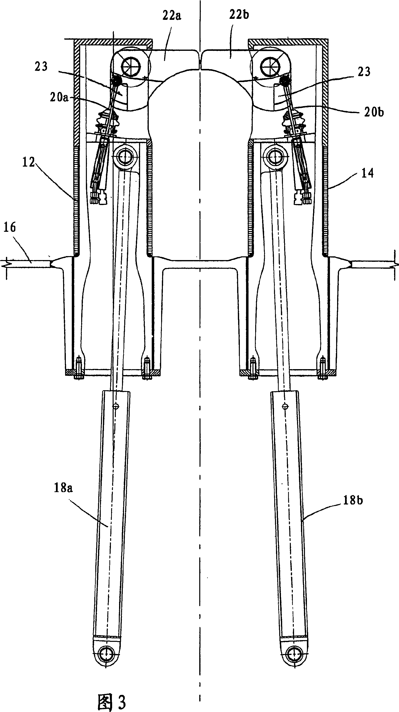
[0022] The drawing shows a drag bolt according to the invention comprising two hoistable and lowerable cylinders 12, 14 mounted in respective grooves in the deck 16 of a ship. Such cylinders include their own pressure rods 18a, 18b, such as a hydraulic cylinder / piston arrangement.

[0023] Figure 2 shows the draw bolt retracted in the deck 16, while Figure 3 shows the draw bolt in its upper working position, ie fully extended position. As shown, pressure rods 18a, 18b can be used for this lifting and lowering motion. Furthermore, each cylinder includes an outwardly rotatable stop 22a, 22b, preferably rotatable about a horizontal axis. The two cylinders are positioned such that their swivel ends approximately contact each other, or abut each other, when the stop is in the fully swiveled position, thereby providing an interior space between the cylinder and the stop for Holds cables.

[0024] The stopper is mounted on a horizontal axis and can be rotated outwards by means of ...


PUM


Abstract

Device for a tow pin to lead a cable, such as a chain, wire, hawser, etc, onboard a vessel, comprising a number of cylinders that can be hoisted and lowered, where each of the cylinders comprises a rotary stopping element, facing each other, to prevent that the cable runs out of the tow pin. Said stopping element can be turned outwards with the help of a piston arrangement arranged in the cylinder, and that the stopping element can be turned outwards in the whole of the working area of the tow pin.

Description

technical field [0001] The invention relates to a drag bolt device for guiding cables such as chains, wires, cables, etc. A stop that prevents the cable from coming out of the hitch. Background technique [0002] The object of the present invention is to provide a draw bolt which meets the existing requirements in the Norwegian offshore area, namely that the draw bolt should withstand a force of 60 degrees on one side wall and an upward force of 30 degrees. Here, force means the maximum pulling force (mooring pull) of the ship. [0003] Another object of the present invention is to provide a towing bolt which can be used as an active tool in handling anchorages in offshore installed anchorages, and which can be used in towing ships and other applications. [0004] Among other things, the invention is advantageous in that the stop of the locking fastener can be driven into or out of an independent position independent of the height position of the drawbar. When the towing ...

Claims


Application Information

Patent Timeline
IPC IPC(8): B63B21/06B63B21/04B63B21/08B63B21/18B63B21/56
CPCB63B21/56B63B21/04B63B21/06B63B21/08B63B21/18
Inventor A·坦德L·K·厄延O·安东森
Owner 康士伯航海公司
Learn More