Engineering machinery transfer equipment with high safety

A technology for construction machinery and transfer equipment, applied in mechanical equipment, motor vehicles, conveyor objects, etc., can solve the problems of reducing the stability of the construction machinery transfer device, reducing the practicability of the construction machinery transfer device, and the construction machinery being heavy and difficult to move, etc. To achieve the effect of safe and stable transfer process, avoiding the interference of unexpected factors, and fixing safety

Inactive Publication Date: 2020-11-24
云和县精达凯玩具设计工作室
View PDF0 Cites 1 Cited by
  • Summary
  • Abstract
  • Description
  • Claims
  • Application Information

AI Technical Summary

Problems solved by technology

[0002] Construction machinery is an important part of China's equipment industry. It is used in earthwork construction projects, road construction and maintenance, mobile lifting and unloading operations, and comprehensive mechanized construction projects required by various construction projects. Most construction machinery is heavy and difficult to move. The construction machinery transfer device is needed during the transfer. The current construction machinery transfer equipment generally puts the machinery directly on the transfer platform during transfer without any protective measures, which reduces the stability of the construction machinery transfer device and is easy for users to use. It brings inconvenience and reduces the practicability of the construction machinery transfer device. This is the deficiency of the existing technology. Therefore, we propose a high-safety construction machinery transfer device

Method used


Image

  • Engineering machinery transfer equipment with high safety
  • Engineering machinery transfer equipment with high safety
  • Engineering machinery transfer equipment with high safety

Examples


Embodiment Construction

[0020] The following description serves to disclose the present invention to enable those skilled in the art to carry out the present invention. The preferred embodiments described below are only examples, and those skilled in the art can devise other obvious variations.

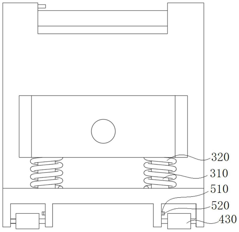
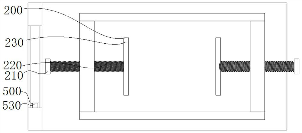
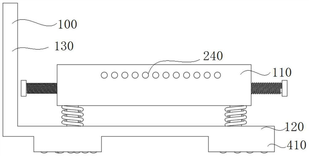
[0021] Please refer to figure 1 As shown in -4, the present invention is a high-safety construction machinery transfer equipment, including a loading device 100, a fixing device 200, a shock absorbing device 300, a moving device 400 and a braking device 500, and the loading device 100 includes a loading box 110 and a carrying plate 120, the loading box 110 is a hollow structure, the fixing device 200 includes a fixing screw 220, one surface of the loading box 110 is provided with a rotating groove, the fixing screw 220 is rotatably matched with the rotating groove, the shock absorbing device 300 includes a fixing column 310, and one end of the fixing column 310 is connected to The lower surface of the loadi...


PUM


Abstract

The invention discloses engineering machinery transfer equipment with high safety, and relates to the technical field of engineering machinery transfer equipment. The engineering machinery transfer equipment with high safety comprises a loading device, fixing devices, a damping device, a moving device and a braking device, wherein the loading device comprises a loading box and a bearing plate; theloading box is of a hollow structure; each fixing device comprises a fixing screw rod; rotating grooves are formed in one surface of the loading box; the fixing screw rods and the rotating grooves are in rotation fit; the damping device comprises fixing columns; one ends of the fixing columns are connected with the lower surface of the loading box; and the other ends of the fixing columns are connected with the upper surface of the bearing plate. According to the engineering machinery transfer equipment with high safety provided by the invention, a device to be transferred is placed in the loading box, then fixing rotary knobs are rotated to clamp an engineering machinery, ropes penetrate into fixing holes to horizontally fix the engineering machinery, and then a push rod is pushed, so that the equipment can be moved; and if an emergency occurs during the transfer, a brake button can also be used to make brake blocks rub rollers to stop the equipment.

Description

technical field [0001] The invention relates to the technical field of construction machinery transfer equipment, in particular to a construction machinery transfer equipment with high safety. Background technique [0002] Construction machinery is an important part of China's equipment industry. It is used in earthwork construction projects, road construction and maintenance, mobile lifting and unloading operations, and comprehensive mechanized construction projects required by various construction projects. Most construction machinery is heavy and difficult to move. The construction machinery transfer device is needed during the transfer. The current construction machinery transfer equipment generally puts the machinery directly on the transfer platform during transfer without any protective measures, which reduces the stability of the construction machinery transfer device and is easy for users to use. It brings inconvenience and reduces the practicability of the construc...

Claims


Application Information

Patent Timeline
Patent Type & Authority Applications(China)
IPC IPC(8): B65G47/90B62B3/02F16F15/067
CPCB62B3/04B62B5/00B62B5/0438B62B5/0476F16F15/067F16F2238/026
Inventor 丁日红
Owner 云和县精达凯玩具设计工作室
Why Eureka
Try Eureka