Fuel injection valve

A technology of fuel injection and fuel oil, which is applied in the direction of fuel injection devices, engine components, machines/engines, etc., and can solve the problems of no fuel cavity and complex structure

Inactive Publication Date: 2006-09-06
DENSO CORP
View PDF2 Cites 3 Cited by
  • Summary
  • Abstract
  • Description
  • Claims
  • Application Information

AI Technical Summary

Problems solved by technology

This structure is not used to reduce the amount of fuel injection, but does not form a fuel chamber
However, this structure with the above-mentioned additional parts on the valve part is relatively complicated

Method used


Image

  • Fuel injection valve
  • Fuel injection valve
  • Fuel injection valve

Examples


Embodiment Construction

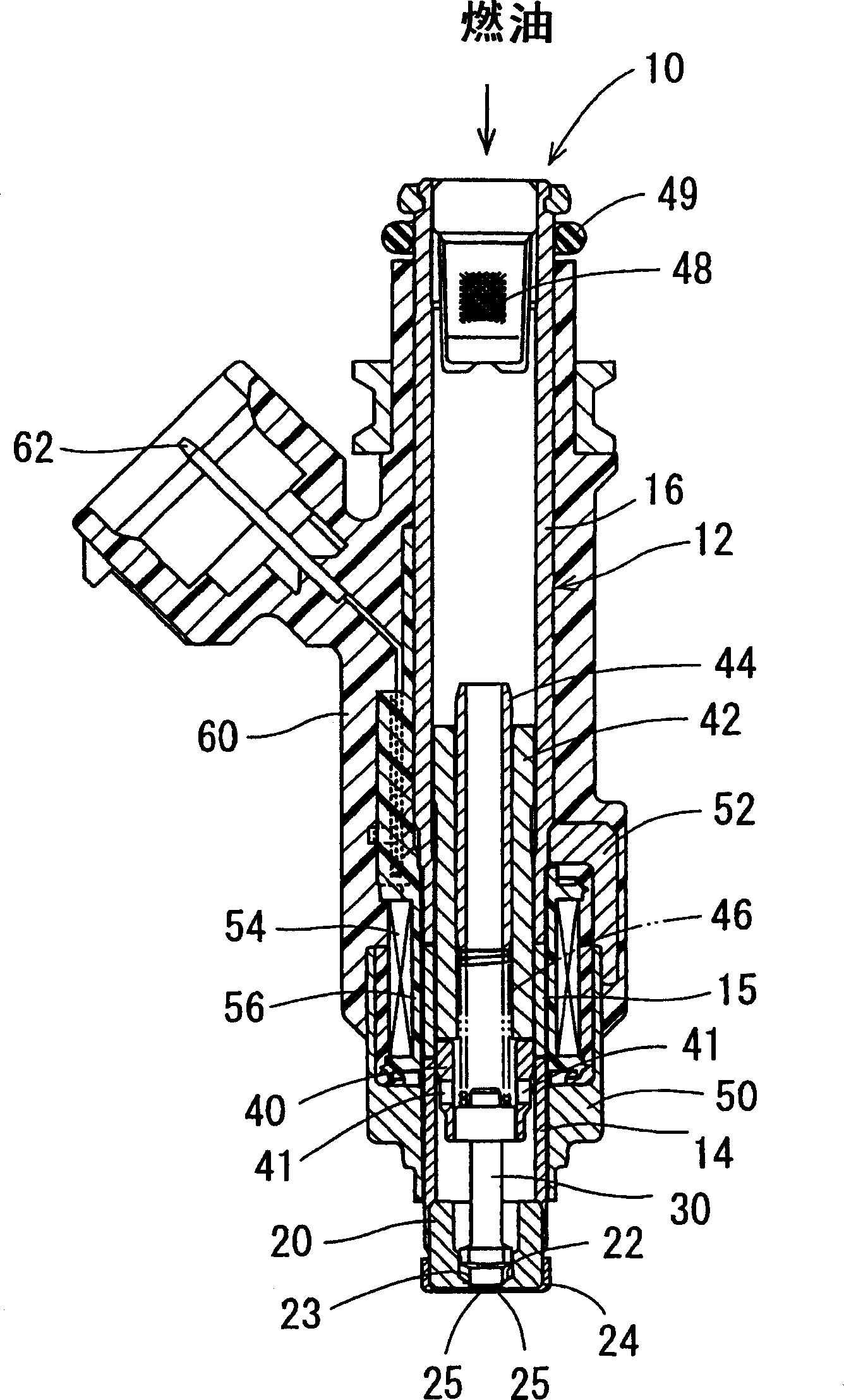
[0019] refer to figure 1 , shows a fuel injection valve according to a first embodiment of the present invention. The fuel injection valve 10 according to this embodiment is applied to an air-cooled engine of a two-wheeled vehicle having an engine displacement of 150 cc or less. The fuel injection valve 10 is located in an intake pipe connected to a combustion chamber of a gasoline engine to inject fuel into intake air flowing through an intake passage defined by the intake pipe. The fuel injection valve 10 is applicable to a direct-injection gasoline engine, which directly injects fuel into a combustion chamber of the gasoline engine. The fuel injection valve 10 is also applicable to diesel engines. The static injection quantity (static injection quantity) of the fuel injection valve 10 is set so that: when the fuel pressure is 300kPa and n-heptane (n-heptane) is used, the static injection quantity becomes 150cm 3 / min or below. In the fuel injection valve 10, the movable...


PUM


Abstract

The invention relates to a fuel injection valve with static injection amount being 150cm3 / min or lower, and it is characterized in that: when valve part is installed on valve seat, the volume of fuel cave limited by the side end face of injection hole of vale part, internal wall surface of vale and inlet side end face of injection hole plate is 0.35mm3 or much lower than that. The distance between the inlet side end face of injection hole plate in vale part and sied end face of injection hole is 0.1mm or larger than that. The diameter of valve seat is 2.7 mm or smaller than that.

Description

technical field [0001] The present invention relates to fuel injection valves for internal combustion engines and similar devices. Background technique [0002] As described in JP-A-2002-257004 or JP-A-2004-124885, such a fuel injection valve is known by placing the valve member on the valve seat formed on the valve body and removing it from the valve seat. Fuel is injected intermittently from the injection hole by disengaging the upper separation valve part. Since engine emission regulations have become stricter in recent years, electromagnetic fuel injection valves mainly used on engines of four-wheeled vehicles are now also applied to various engines such as engines of two-wheeled vehicles. [0003] When the valve member is seated on the valve seat, a fuel chamber as a dead volume is formed between the tip end surface of the valve member on the injection hole side and the inlet of the injection hole. In such a fuel injection valve, if the temperature of the engine rises...

Claims


Application Information

Patent Timeline
IPC IPC(8): F02M51/00
Inventor 外尾隆幸杉山幸一山本辰介
Owner DENSO CORP
Why Eureka
Try Eureka