Passive zero breaking automatic de-excitation device and method

A demagnetization and switching technology, applied in emergency protection circuit devices, electrical components, etc., can solve problems such as switch burnout, accident expansion, equipment damage, etc., to suppress output harmonics and improve EMN/EMC effects

Active Publication Date: 2006-09-06
CHINA YANGTZE POWER
View PDF0 Cites 2 Cited by
  • Summary
  • Abstract
  • Description
  • Claims
  • Application Information

AI Technical Summary

Problems solved by technology

However, the capacity and electrical parameters of the high peak value and high power static rectification excitation system commonly used in modern large and super large synchronous generators, especially hydroelectric units, are no longer comparable to those of small and medium capacity units in the past, but their demagnetization devices and technologies are still Continue to use the original strong switch to block the transfer of magnetic field current to the demagnetization resistor. Looking at domestic and foreign new and old power plants, there are almost no exceptions. That is to say, the success or failure of generator demagnetization depends entirely on the mechanical and mechanical properties of the magnetic field switch. Electrical performance, thus forming an absolute dependence on the magnetic field switch. Although there have been some improvement measures in recent years, they can only alleviate the pressure of insufficient electrical strength of the magnetic field switch, and cannot fundamentally solve the problem, especially in modern high-power Static rectifier excitation system is very prone to de-excitation under the condition of out-of-control and false strong excitation, which often leads to serious consequences such as switch burnout, equipment damage, and accident expansion

Method used


Image

  • Passive zero breaking automatic de-excitation device and method
  • Passive zero breaking automatic de-excitation device and method
  • Passive zero breaking automatic de-excitation device and method

Examples


Embodiment Construction

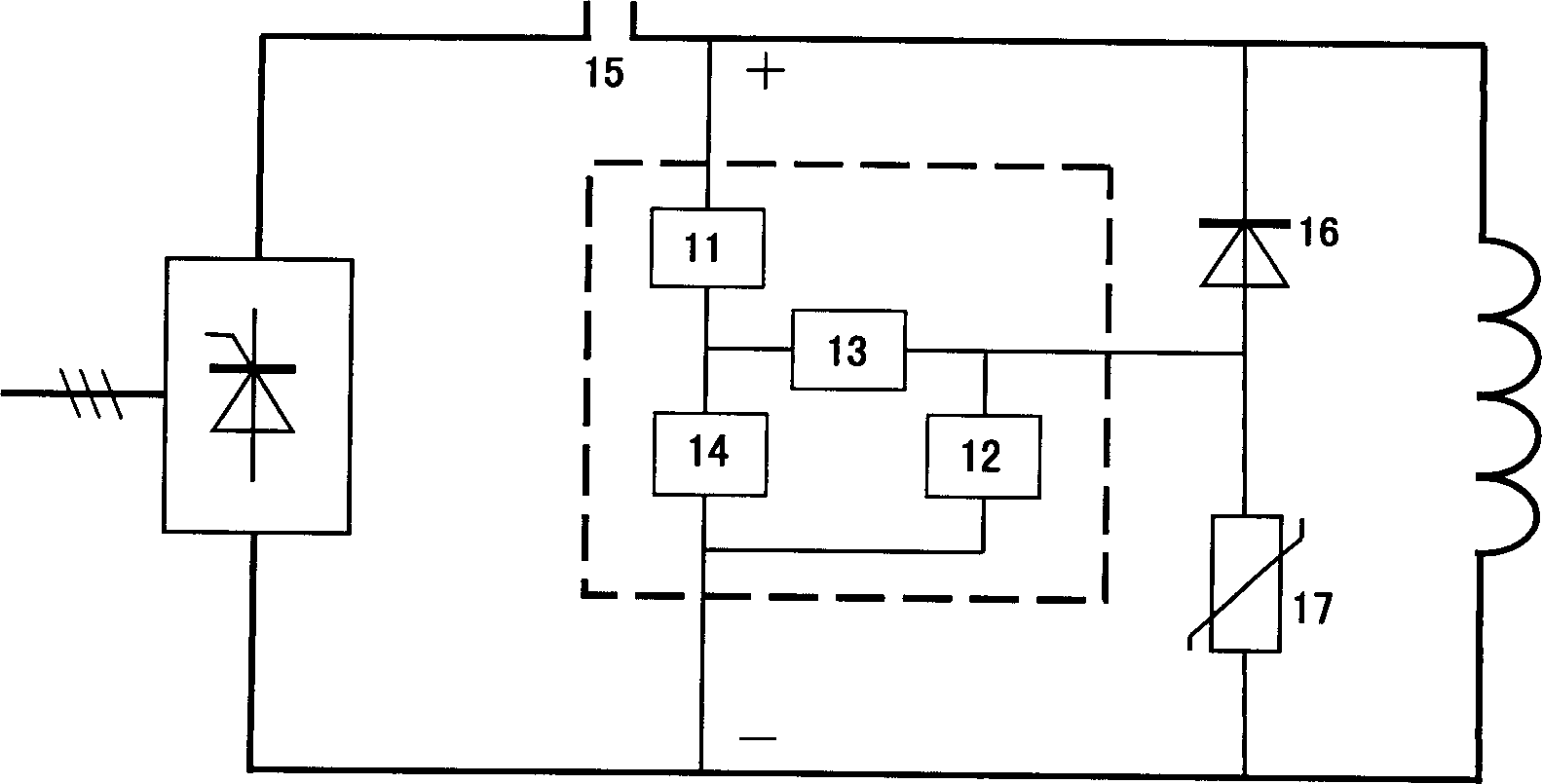
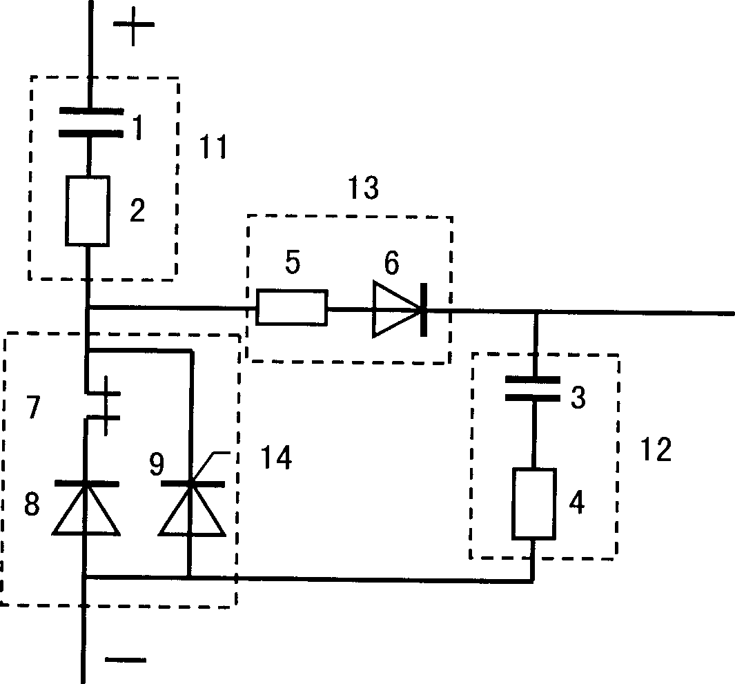
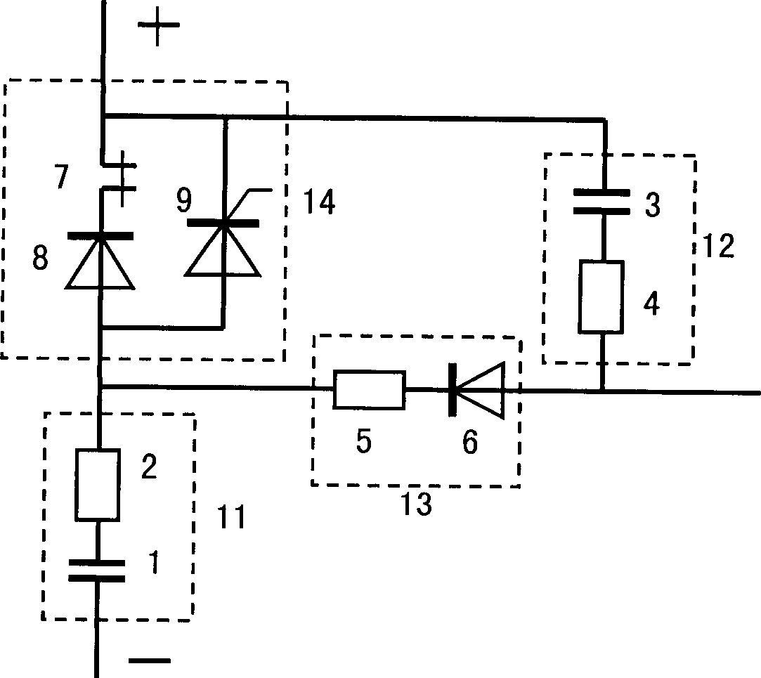
[0027] The circuit of the present invention has two implementation modes such as figure 2 , image 3 , wherein the functions of each functional group device are the same, the main charge and discharge capacitor (1) is connected in series with the adjustment resistor (2) to form a discharge transfer function group (11); the auxiliary charge and discharge capacitor (3) is connected in series with the current limiting resistor (4) , to form a reverse pressure superposition function group (12); the main charging channel resistor (5) is connected in series with the main charging diode (6) to form a channel isolation function group (13); the magnetic field switch associated normally closed contact (7) is connected in series with a diode (8 ) is then connected in parallel with the thyristor switch (9) to form a dual start function group (14). After receiving the external demagnetization command, the magnetic field switch will be disconnected, and its linkage normally closed contact...


PUM


Abstract

The present invention discloses passive zero on/off automatic excitation cut-off device and method. Said invention utilize passive electric power electronic device assembling plurality of function group to form topology network connection, providing powerful absorbing harmonic overvoltage function, once receiving demagnetization instruction, double starting up function group action, switching-on function discharging channel, function group rapid discharging transferring magnetic field current, reverse charging establishing voltage to conduct demagnetization resistor to complete demagnetization. Said invention can greatly improve demagnetization performance and save cost by more than 50 per cent.

Description

technical field [0001] The invention is applied to accident forced demagnetization technology of rotor magnetic field of large synchronous generator, especially for high-power thyristor rectification and excitation system. (Search Category H02H-7 / 00-7 / 06-7 / 09-7 / 125-7 / 127) Background technique [0002] Large-scale synchronous generators (including hydropower and thermal power units), in the event of an emergency, must quickly trip and demagnetize to protect the safety of the unit equipment to the greatest extent. However, the capacity and electrical parameters of the high peak value and high power static rectification excitation system commonly used in modern large and super large synchronous generators, especially hydroelectric units, are no longer comparable to those of small and medium capacity units in the past, but their demagnetization devices and technologies are still Continue to use the original strong switch to block the transfer of magnetic field current to the de...

Claims


Application Information

Patent Timeline
Patent Type & Authority Applications(China)
IPC IPC(8): H02H7/06
Inventor 黄大可潘家才邵显钧
Owner CHINA YANGTZE POWER
Why Eureka
Try Eureka