Mixing system

A technology of mixing systems and mixing elements, applied in the field of mixing systems, can solve problems such as pressure drop, and achieve the effect of high adaptability and high flexibility

Active Publication Date: 2006-09-06
YARA ENVIRONMENTAL TECH GMBH
View PDF0 Cites 12 Cited by
  • Summary
  • Abstract
  • Description
  • Claims
  • Application Information

AI Technical Summary

Problems solved by technology

The disadvantage of this hybrid system is that the pressure drop generated by the hybrid system is relatively high due to the strong turbulence of the fluid in the single discharge line

Method used


Image

  • Mixing system
  • Mixing system
  • Mixing system

Examples


Embodiment Construction

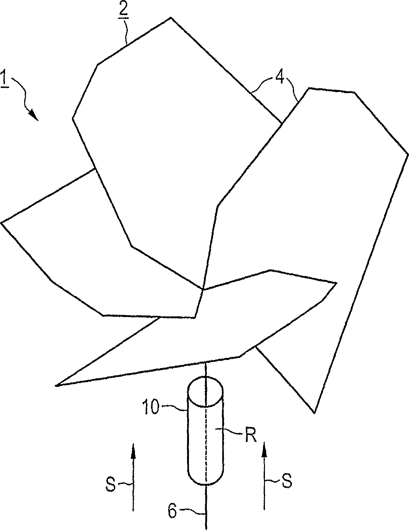
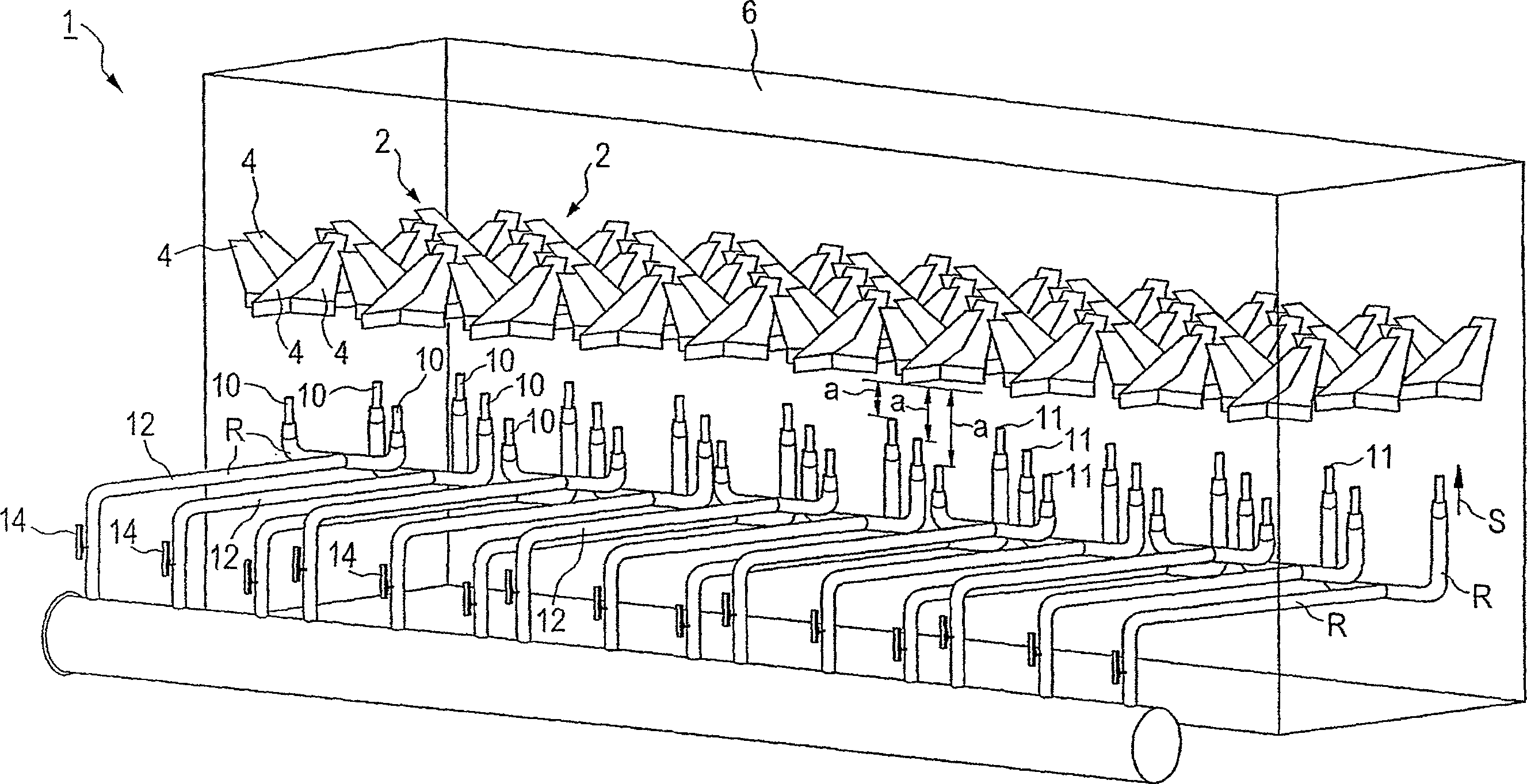
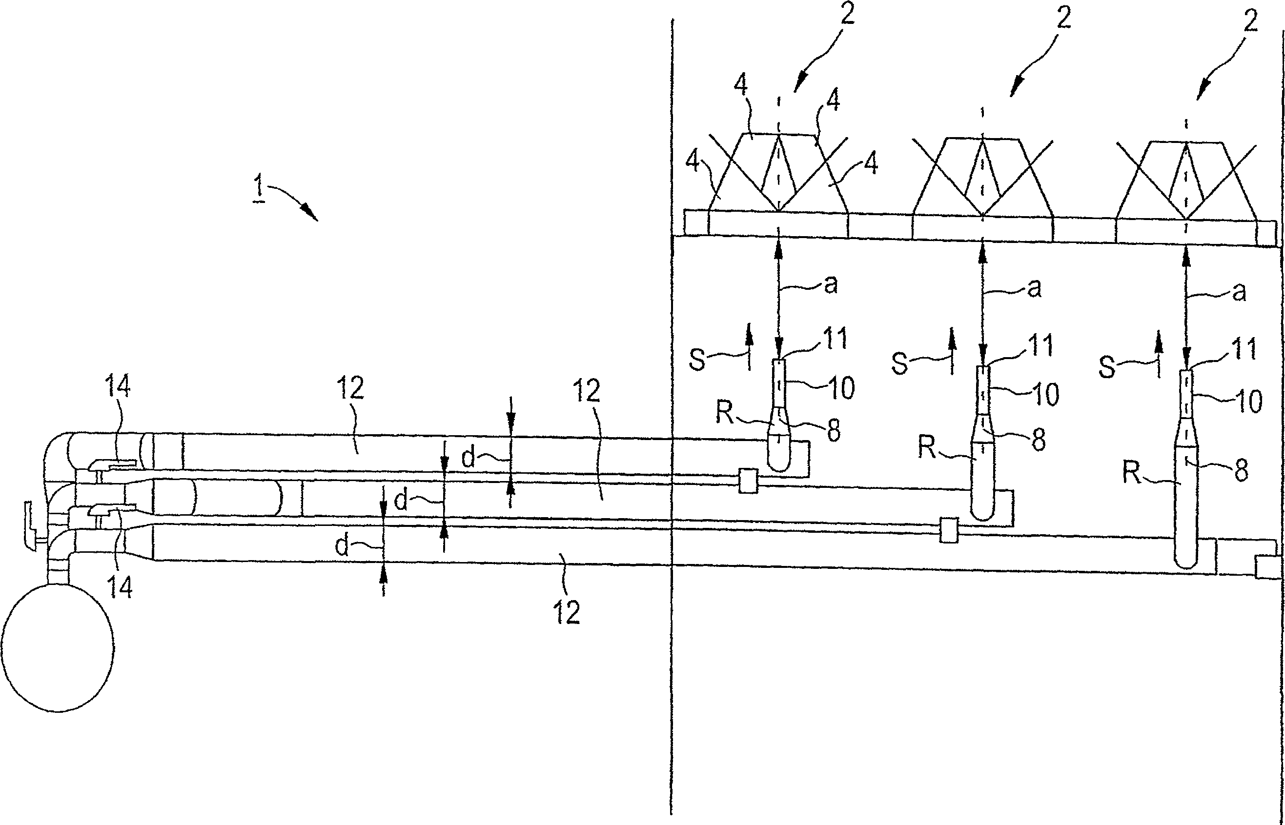
[0032] exist Figure 1 to Figure 3 The mixing system 1 shown in includes a plurality of mixing elements 2 arranged in the form of a fence in the assembly surface, in figure 1 Only one mixing element 2 is shown in the image 3 Three mixing elements 2 are shown in . In the exemplary embodiment, the mixing element 2 consists of four inclined mixing blades 4 which are arranged around the central axis 6 of the mixing element 2 . The mixing blades 4 serve to generate a vortex of the flow medium S conducted in the flow line 6 upstream of the mixing element 2 . In this way the vortex passes through the mixing blade 4 formed in the figure 2 The axial deflection of the flow duct 6 shown in and the flow medium S flowing parallel to the center axis 8 are formed in the tangential direction of the flow duct 6 and homogenize the flow medium. In order to achieve a stable mixing effect, the mixing blades 4 are arranged with one another at a constant staggered angle. In an embodiment this...


PUM

PropertyMeasurementUnit
Overlap degreeaaaaaaaaaa

Abstract

A mixing system should, while effecting a homogeneous mixing with a low loss of pressure, have a short intermixing distance. The mixing system contains mixing elements disposed in a flow channel and have mixing blades disposed around a respective central axis. Adjacent mixing blades each have an overlap in their plane of projection to the normal plane of the central axis. An injection location for supplying a reaction medium is connected upstream from some or all of the mixing elements. The injection location is dimensioned such that the reaction medium, at its discharge from the injection location, has a discharge velocity that is increased by an excess factor with regard to the flow medium inside the flow channel. The mixing elements are dimensioned such that the quotient of the degree of overlap of adjacent mixing blades (in percent) and of the excess factor ranges from 0.1 to 5.

Description

technical field [0001] The invention relates to a mixing system having a plurality of mixing elements arranged in a flow duct, the mixing elements having a plurality of mixing blades arranged around a respective central axis, wherein adjacent mixing blades of the mixing elements are each There is an overlap of their projection planes in the plane normal to the center axis, with some or all mixing elements in the flow duct being preceded by at least one injection device for the supply of the reaction medium. Background technique [0002] The reaction medium flowing in through the injection device is evenly distributed by means of mixing blades. The injection device can be designed, for example, as a pipe connection with a nozzle as a connecting connection, with which the reaction medium introduced is atomized and thus distributed rapidly and as uniformly as possible in the flow medium. Thus, for example, different previously introduced gases can be mixed with one another. S...

Claims


Application Information

Patent Timeline
Patent Type & Authority Applications(China)
IPC IPC(8): B01F5/04B01F3/04B01D53/86B01D53/56B01D53/79B01F5/06
CPCB01F5/0453B01F3/0446B01F5/0456B01F2215/0427B01D53/8631B01F5/0616B01F5/0451B01D53/56B01F2215/0409B01F23/232B01F25/31322B01F25/3132B01F25/3131B01F25/4315B01F25/43151
Inventor 迪尔克·瓦尔特理查德·布丁克劳斯·魏格尔英戈·甘茨曼
Owner YARA ENVIRONMENTAL TECH GMBH
Why Eureka
Try Eureka