Disk loading device

A disc and trigger lever technology, applied in the direction of instruments, record carrier structural parts, data recording, etc., can solve the problems that it is difficult to realize the thinning or miniaturization of the disc loading device, and the complex structure

Inactive Publication Date: 2006-09-13
PANASONIC CORP
View PDF1 Cites 0 Cited by
  • Summary
  • Abstract
  • Description
  • Claims
  • Application Information

AI Technical Summary

Problems solved by technology

However, in such a configuration, since a plurality of mechanism parts are required in conjunction with the operation of the insertion detection lever, the structure is complicated, and it is difficult to reduce the thickness or size of the disk loading device.

Method used


Image

  • Disk loading device
  • Disk loading device
  • Disk loading device

Examples


Embodiment Construction

[0032] Before proceeding with the description of the present invention, it should be noted that the same reference numerals are attached to the same components in the drawings for convenience of description.

[0033] In addition, in the present invention, the disc loading device refers to a device that inserts a disc-shaped recording medium into the device and mounts it at a mounting position of the disc in order to perform recording and reproduction on the disc-shaped recording medium. Examples of the above-mentioned recording medium include various optical discs for computers such as CDs which are optical discs for audio and DVDs which are optical discs for video.

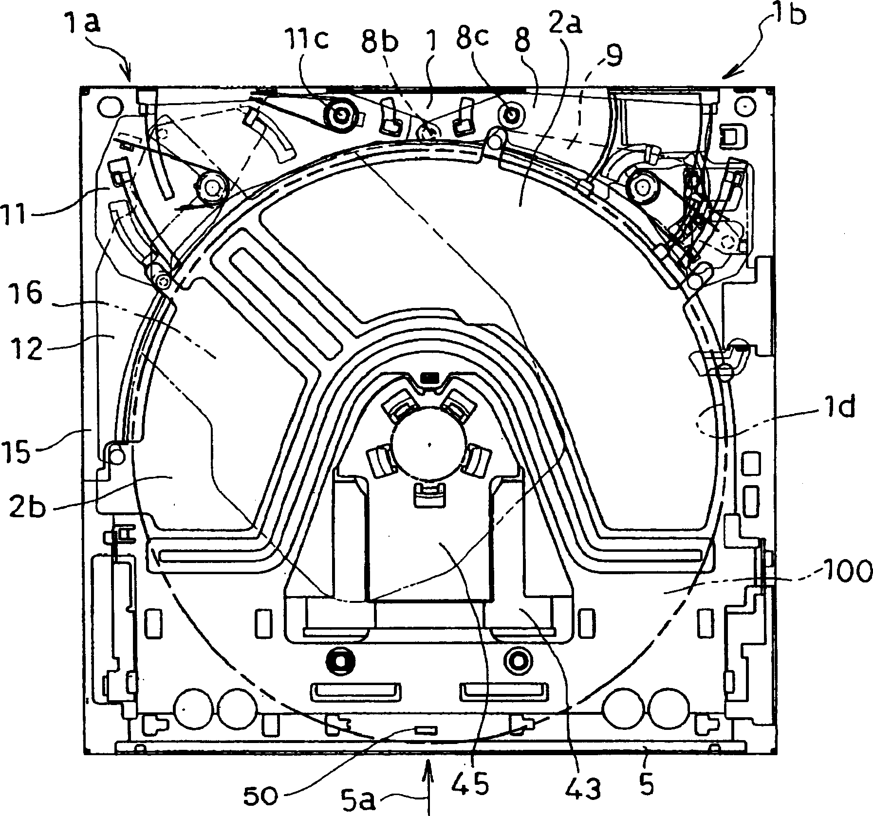
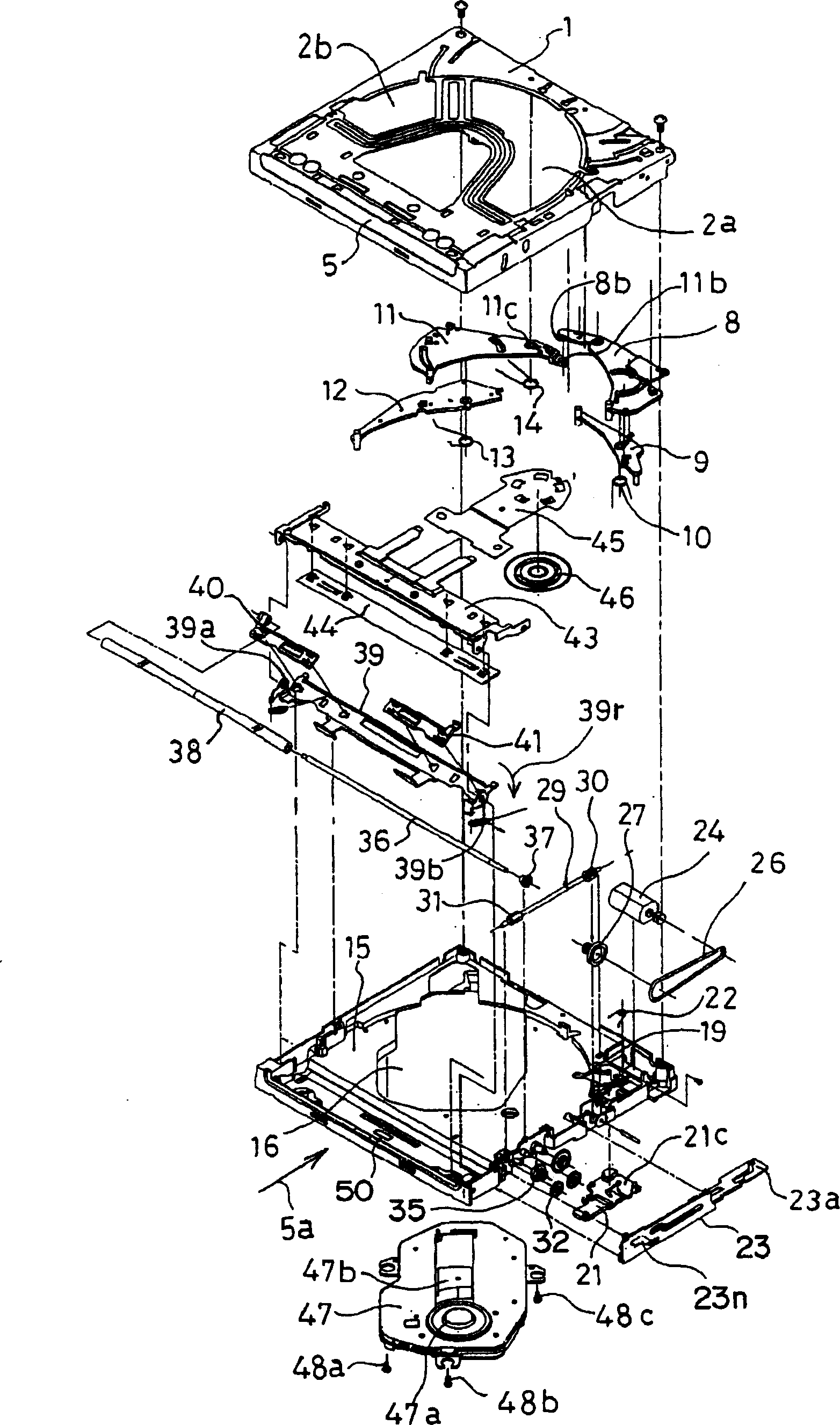
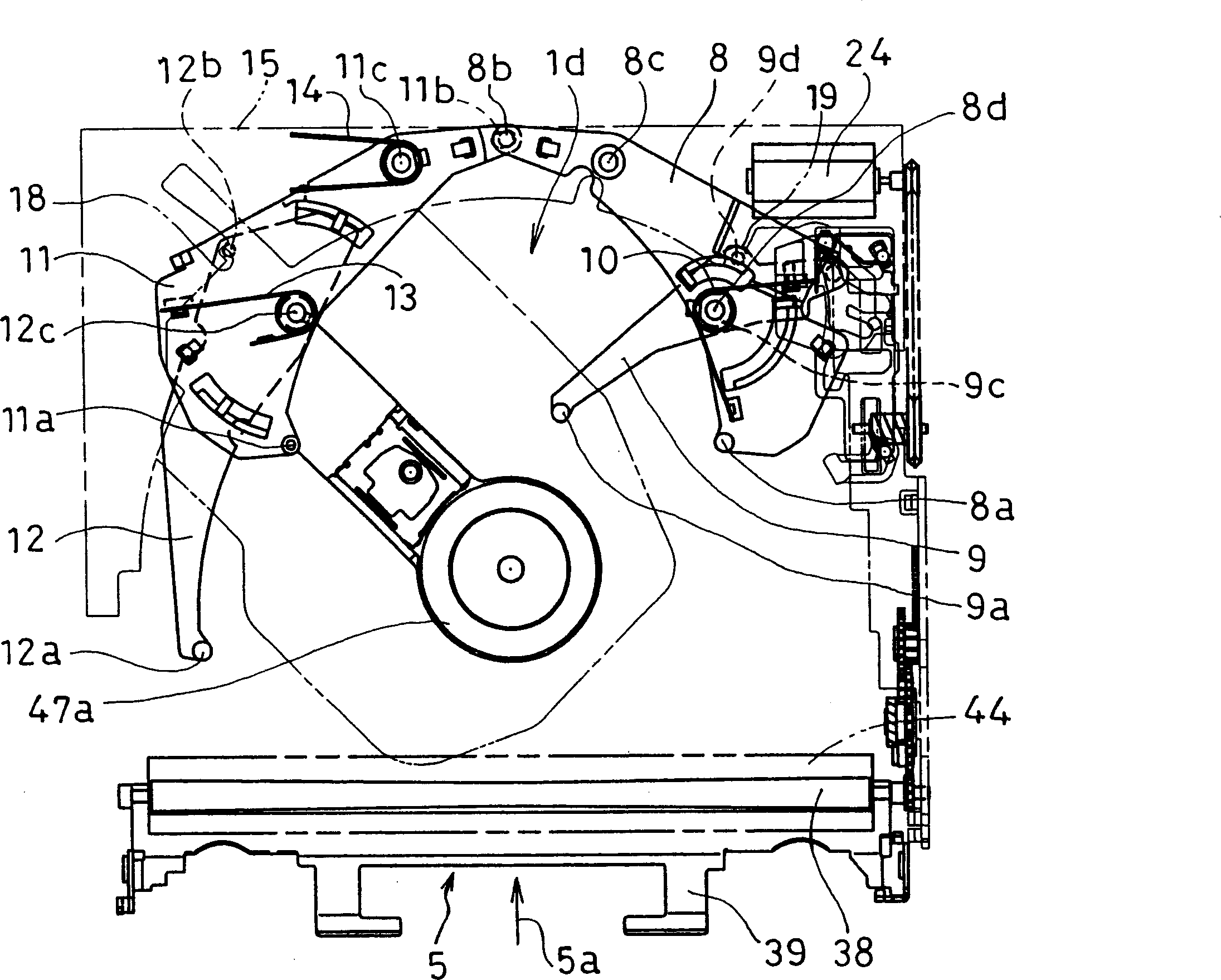
[0034] refer to Figure 1 to Figure 18 A preferred disk loading device of the present invention will be described.

[0035] figure 1 is a plan view of the disk loading device of this embodiment, figure 2 is its exploded perspective view. Figure 3 ~ Figure 6 It is a plan view showing an operation when a disc...


PUM


Abstract

The invention provides a disk loading device, which has: a positioning lever (8) whose positioning pin (8a) is in contact with the outer periphery of the disk (100); The pin (9a) is in contact with the outer circumference of the disc (100) and rotates the trigger lever (9); the trigger lever (21) is displaced in conjunction with the rotation of the trigger lever (9); has a cam (23a) and is triggered by transmission A cam lever (23) for initial movement due to displacement of the lever (21); a driving device for driving the cam lever (23) to move after the initial movement of the cam lever (23). By using the driving device to move the cam lever (23), the trigger lever (21) moves along the cam (23a), and the engagement pin (9a) of the trigger lever (9) is disengaged from the disc (100).

Description

technical field [0001] The present invention relates to a disc loading device for inserting a disc-shaped recording medium into the device and installing it at a disc mounting position. Background technique [0002] The disc loading device is used for optically recording and reproducing data on various optical discs for computers, such as audio discs, namely CDs, and video discs, namely DVDs. The disc is inserted into the device and installed in the The device of the installation position of the disk is widely used in various fields. Among the optical discs described above, there are two types of optical discs that are used as bare discs that are not loaded into a cartridge, discs with a diameter of 12 cm (large diameter disc) and discs with an 8 cm diameter (small diameter disc). In a disk loading device that mounts such a disk, it is necessary to correctly position the disk at a mounting position in the device. A typical conventional example of such a positioning device ...

Claims


Application Information

Patent Timeline
IPC IPC(8): G11B17/051G11B33/00
Inventor 森冈幸生石川和雄吉田则胜山崎卓人
Owner PANASONIC CORP
Why Eureka
Try Eureka