Supercharge Your Innovation With Domain-Expert AI Agents!

Devices and methods for producing multiple x-ray beams from multiple locations

A generation device, X-ray technology, applied to X-ray tube components, X-ray tubes, X-ray tube electrodes, etc., can solve the problems of limited observation angle, slow speed, and inability to generate multiple images at the same time, achieving flexible The effect of controllability

Active Publication Date: 2010-06-16
NURAY TECH
View PDF15 Cites 0 Cited by
  • Summary
  • Abstract
  • Description
  • Claims
  • Application Information

AI Technical Summary

Problems solved by technology

[0009] Although the techniques described above can serve this purpose, these single electron beam based x-ray inspections have several disadvantages related to limited resolution, limited viewing angle, cost and efficiency
These prior art devices and techniques have a common disadvantage in that they all rely on a single electron source to generate x-rays and acquire multiple images of the printed circuit board from different angles
Therefore, they are inherently slow and cannot simultaneously produce multiple images of the detected object from different angles
In addition, they all mechanically move the x-ray source or x-ray detector, which will result in inconsistent x-ray focus size and image quality
Also, these x-ray systems all rely on thermionic emitters, which are temperature sensitive, require long warm-up times, and are not easy to turn on / off, so they are not easy to program, a lot of wasted energy, and x-ray system lifetime

Method used


Image

  • Devices and methods for producing multiple x-ray beams from multiple locations
  • Devices and methods for producing multiple x-ray beams from multiple locations
  • Devices and methods for producing multiple x-ray beams from multiple locations

Examples


Embodiment Construction

[0045] Exemplary devices and techniques of the present invention are described below with reference to the accompanying figures.

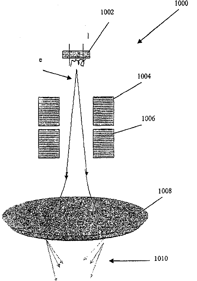
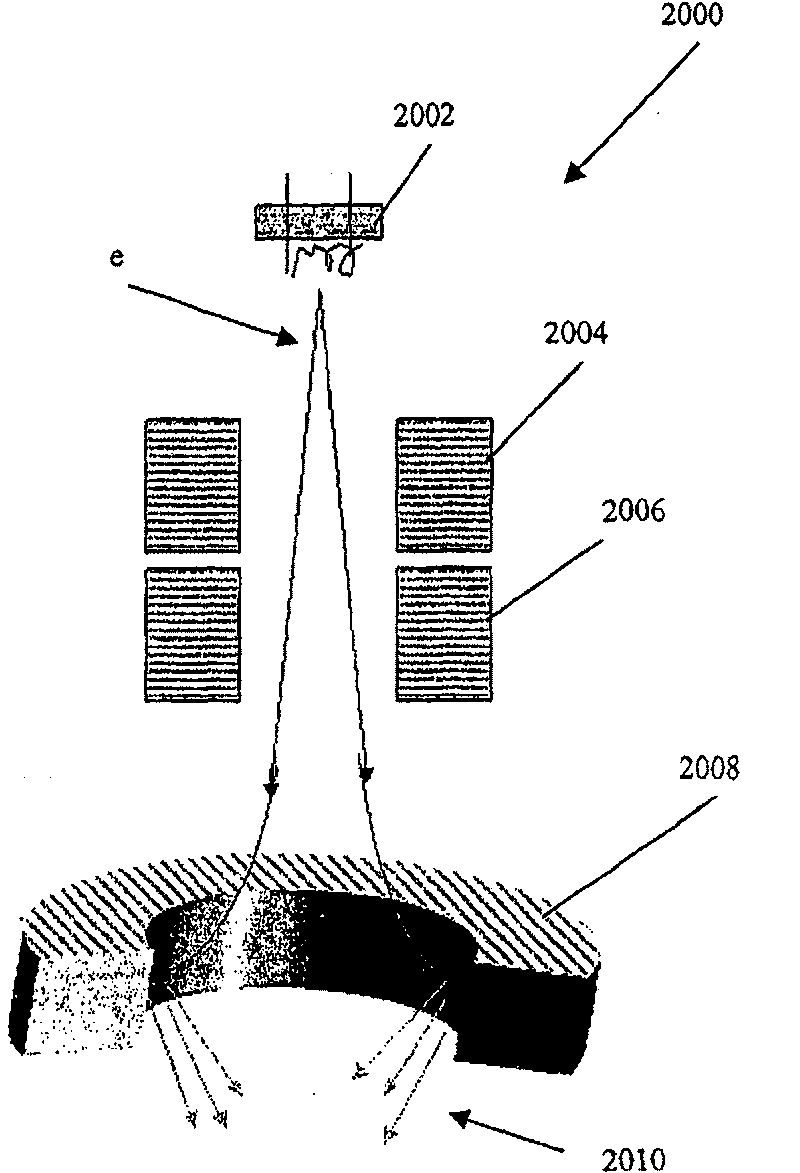
[0046] According to one embodiment of the present invention, such as Figure 5 As shown, the x-ray source comprises a field emission cathode 12 having a plurality of independently addressable electron emitting elements or "pixels" 11 . Cathode 12 has as Figure 6 The plane geometry shown. Anode 13 is opposed thereto and is separated from cathode 12 in vacuum chamber 14 by a finite gap distance. Electron emission from the pixel 11 on the cathode can be controlled by the gate electrode. Possible gate structures and arrangements used in this and other embodiments will be described in detail later. The X-ray source may comprise a single grid electrode, or more preferably comprises a grid electrode provided with a plurality of independently addressable cells, each cell controlling a respective pixel 11 on the cathode 12 . Electrons are extracted fr...


PUM


Abstract

A multi-beam x-ray generating device includes a stationary field-emission cathode having a plurality of stationary and individually controllable electron-emitting pixels disposed in a predetermined pattern on the cathode, an anode opposing the cathode comprising a plurality of focal spots disposed in a predetermined pattern that corresponds to the predetermined pattern of the pixels, and a vacuumchamber enveloping the anode and cathode. An additional construction is in the form of an a x-ray generating device including a stationary field-emission cathode, the cathode having a planar surface with an electron-emissive material disposed on at least a portion thereof, a gate electrode disposed in parallel spaced relationship relative to the planar surface of the cathode, the gate electrode having a plurality of openings having different sizes, an anode opposing the cathode and spaced therefrom, the anode having a plurality of focal spots aligned with the electron-emissive material, and avacuum chamber enveloping the anode and cathode, wherein the gate electrode is operable such that the openings can be manipulated to bring at least one beam of electrons emitted from the cathode intoand out of registry with at least one of the focal spots. Associated methods are also described.

Description

technical field [0001] The present invention relates to apparatus and methods for generating multiple X-ray beams from multiple locations. For example, methods and apparatus are contemplated that employ field emission cathodes having a plurality of individually addressable electron emission pixels. Electrons emitted from the pixels can be directed to different focal points on the anode, creating multiple x-ray beams from multiple locations on the same device. Background technique [0002] Various structures and techniques are described below. However, nothing described herein is to be taken as an admissions of prior art. On the contrary, the applicant has the right to prove that what is described herein is not prior art under the applicable legal provisions when appropriate. [0003] A traditional X-ray tube consists of a cathode, an anode and a vacuum envelope. The cathode is the negative electrode used to project electrons onto the positive anode. The anode attracts a...

Claims


Application Information

Patent Timeline
Patent Type & Authority Patents(China)
IPC IPC(8): H01J35/06H05G
CPCH01J35/065H01J2235/068
Inventor Q·秋J·卢O·Z·周
Owner NURAY TECH
Features
  • R&D
  • Intellectual Property
  • Life Sciences
  • Materials
  • Tech Scout
  • Unparalleled Data Quality
  • Higher Quality Content
  • 60% Fewer Hallucinations
Learn More