Active matrix type display device and driving method thereof

A display device and active matrix technology, applied in lighting devices, static indicators, instruments, etc., can solve the problem of extinguishing organic EL components 216, and achieve the effects of improving display quality, suppressing afterimages, and suppressing bad bright spots

Active Publication Date: 2006-09-27
SANYO ELECTRIC CO LTD
View PDF1 Cites 0 Cited by
  • Summary
  • Abstract
  • Description
  • Claims
  • Application Information

AI Technical Summary

Problems solved by technology

On the other hand, when the TFT 214 for driving becomes non-conductive in response to the display signal D supplied to the gate, since no current flows through the TFT 214 for driving, the organic EL element 216 is turned off.

Method used


Image

  • Active matrix type display device and driving method thereof
  • Active matrix type display device and driving method thereof
  • Active matrix type display device and driving method thereof

Examples


Embodiment Construction

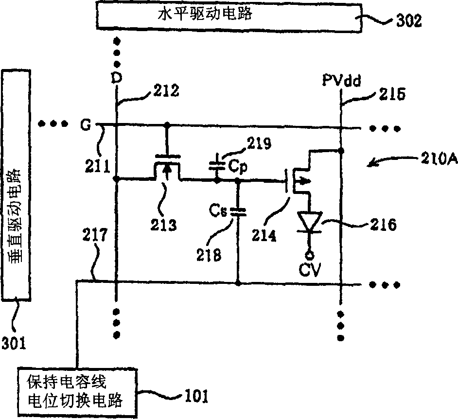
[0053] Next, an active matrix organic EL display device and a driving method thereof according to a first embodiment of the present invention will be described with reference to the drawings. figure 1 It is an equivalent circuit diagram of the organic EL display device according to this example. figure 1 Only one display pixel 210A among several pixels arranged in a matrix on the display panel is shown. figure 1 in, with Figure 11 The same components are assigned the same reference numerals and their descriptions are omitted.

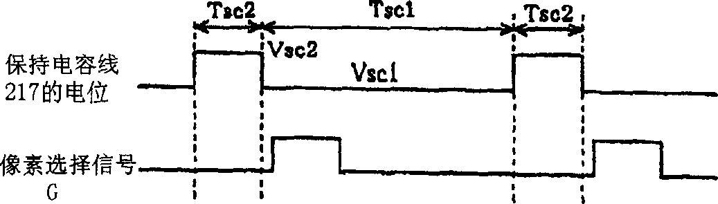
[0054] Such as figure 1 As shown, this organic EL display device includes: a storage capacitor line potential switching circuit 101 connected to a storage capacitor line 217 of a display pixel 210A. The storage capacitance line potential switching circuit 101 switches the potential of the storage capacitance line 217 from the first potential Vsc1 to the second potential Vsc2 higher than the first potential Vsc1, makes the TFT 214 for driving non-...


PUM


Abstract

A residual image effect is suppressed to improve quality of display of an active matrix type display device. A capacitor line electric potential switching circuit switches an electric potential of a capacitor line from a first capacitor electric potential Vsc 1 to a second capacitor electric potential Vsc 2 that is higher that the first capacitor electric potential Vsc 1 , while a power supply electric potential switching circuit switches an electric potential of a power supply line from a first power supply electric potential PVdd 1 to a second power supply electric potential PVdd 2 that is lower than the first power supply electric potential PVdd 1 . As a result of synergistic effect, an electric potential Vg at a gate of a driver TFT becomes higher than an electric potential at its source by more than a threshold voltage Vtp of the driver TFT. Assuming carriers are trapped in a gate insulation film of the driver TFT due to writing-in of a display signal in a preceding frame period, the carriers are extracted from the gate insulation film to the source or a drain of the driver TFT. With this, electric characteristics of the driver TFT are initialized.

Description

technical field [0001] The present invention relates to an active matrix type display device and a driving method thereof. Background technique [0002] In recent years, an organic EL display device using an organic electroluminescence device (Organic Electro Luminescence Device: hereinafter abbreviated as [organic EL device]) to replace the CRT and LCD display devices has been developed. In particular, an active matrix organic EL display device having a thin film transistor (Thin Film Transistor: hereinafter abbreviated as [TFT]) as a switching element driven as an organic EL element has been developed. [0003] Hereinafter, an active matrix organic EL display device will be described with reference to the drawings. Figure 11 An equivalent circuit diagram of the organic EL display device is shown. exist Figure 11 Only one display pixel 210 among several display pixels arranged in a matrix on the display panel is shown in . [0004] An N-channel TFT 213 for selecting a p...

Claims


Application Information

Patent Timeline
Patent Type & Authority Applications(China)
IPC IPC(8): G09G3/30G09G3/20H05B33/08H05B33/14H05B44/00
CPCY02B20/346Y02B20/343
Inventor 小川隆司
Owner SANYO ELECTRIC CO LTD
Why Eureka
Try Eureka