
Distribution switchboard

A technology of distribution board and conductive board, which is applied in the direction of electrical components, substation/switch layout details, etc., to achieve the effect of easy connection and space saving

Inactive Publication Date: 2011-01-26
MATSUSHITA ELECTRIC WORKS LTD
View PDF1 Cites 0 Cited by
  • Summary
  • Abstract
  • Description
  • Claims
  • Application Information

AI Technical Summary

Problems solved by technology

[0003] However, when connecting each branch circuit breaker with a neutral pole and a voltage pole, there is a problem: the voltage pole must be connected to the conductive bar close to each branch circuit breaker, and it cannot be connected to a conductor bar far away from each branch circuit breaker. Conductor strips for branch circuit breakers

Method used


Image

  • Distribution switchboard
  • Distribution switchboard
  • Distribution switchboard

Examples


Embodiment Construction

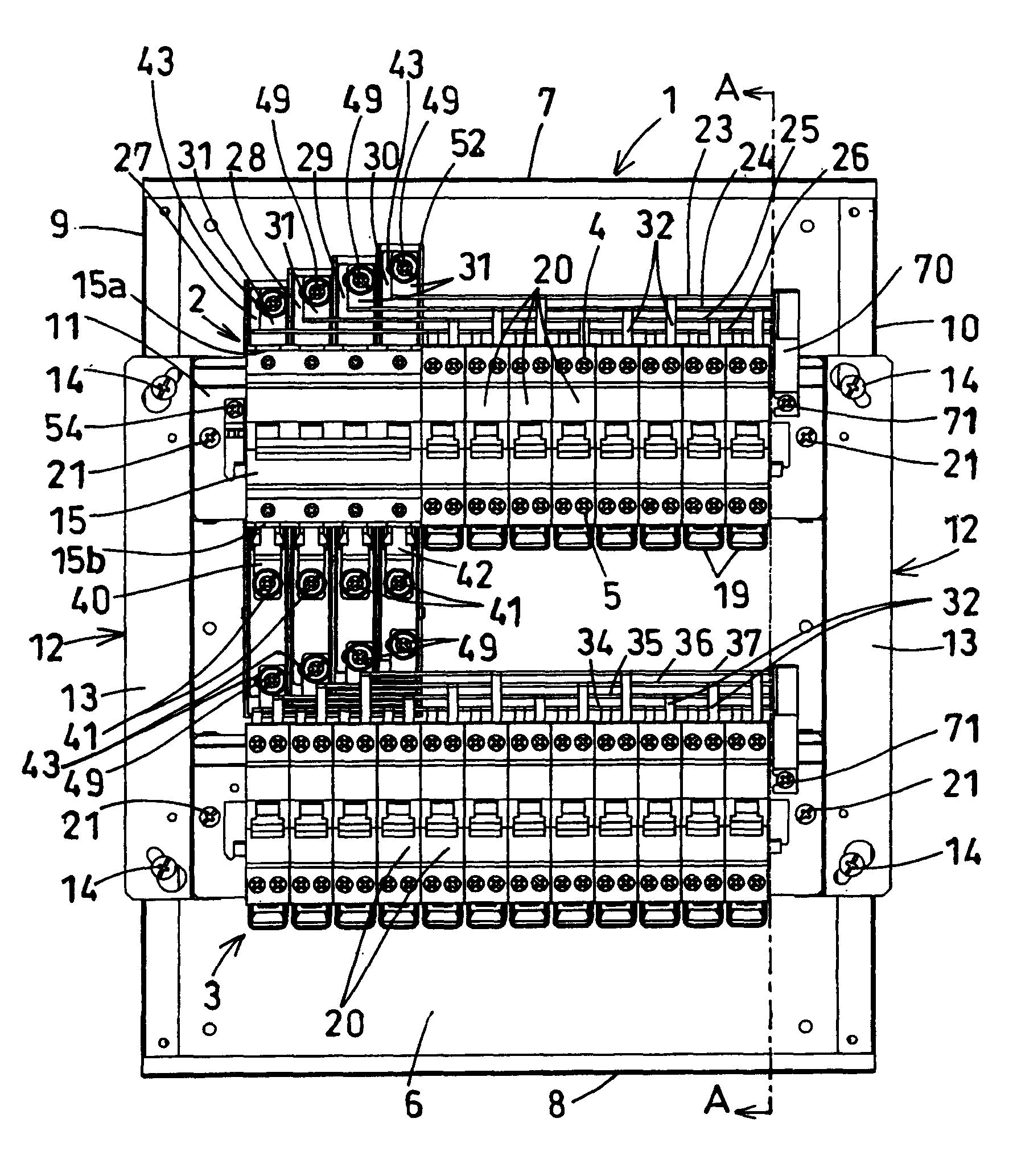
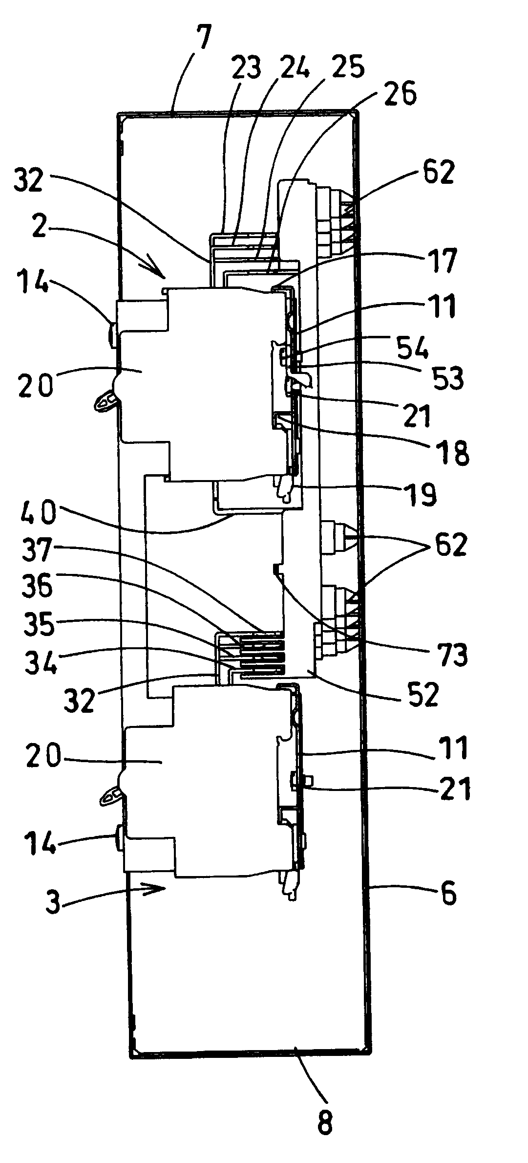
[0039] According to from Figure 1 to Figure 12 A first embodiment of the invention will be described. The switchboard is installed, for example, in a three-phase four-wire distribution line connecting loads between the voltage poles U, V, W and the neutral pole N. The distribution board is provided with a first internal device block 2 and a second internal device block 3 in the box body 1 .

[0040] The housing 1 is a housing having upper, lower, left, and right side plates 7 to 10 erected from a bottom plate 6 and its surroundings, with one surface opening.

[0041] The first internal device block 2 sets the input and output terminals 4, 5 in the direction of the upper and lower side plates 7, 8 of the box body 1, and arranges a plurality of branch circuit breakers 20 on the left and right side plates 9, 10 of the box body 1 direction, and arrange them side by side on the substrate 11. The base plate 11 is installed on the connecting sheet by bolts 21, and the connecting ...


PUM


Abstract

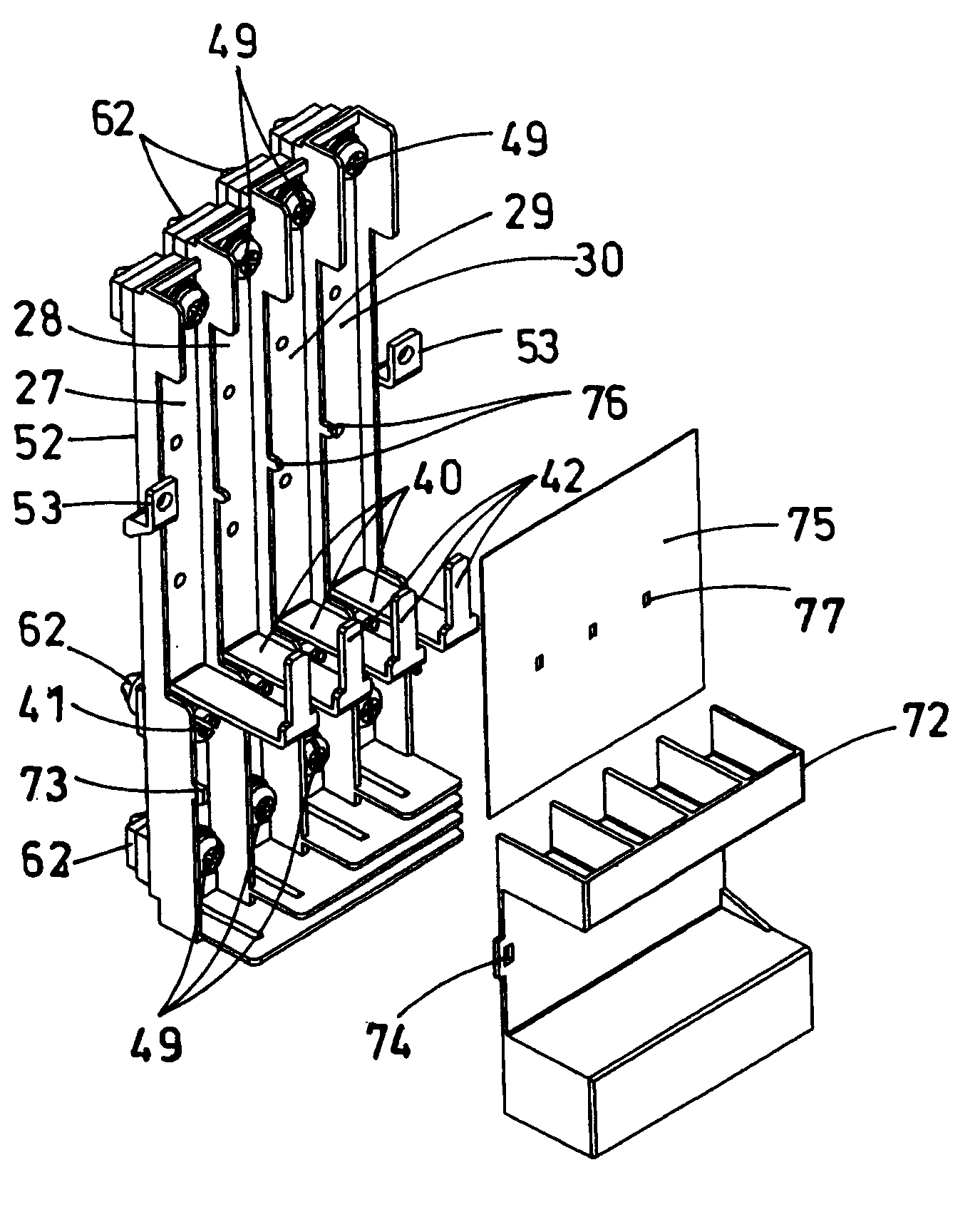
The present invention provides a distribution board which can easily connect a branch breaker to any voltage pole no matter which branch breaker between top and bottom it may be. The first inner receptacle block 2 has a plurality of branch breakers 20 juxtaposed in a row within a box 1, and the input terminals 4 of each branch breaker stand in a line on one side. The second inner receptacle block3 is the same, and it stands in a line with the first inner receptacle block. The first two or more branch bars 23-26 are arranged to parallel the side of the input terminals 4 of the first inner receptacle block 2, and are connected to the input terminals 4 of the first receptacle block 2. The second two or more branch bars 34-37 are also connected to the input terminals of the second inner receptacle block 3. A plurality of trunk bars 27-30 are connected with the first branch bars and the second branch bars, passing between the first inner receptacle block 2 and the bottom plate 6 of the box 1.

Description

technical field [0001] The invention relates to a distribution board in which branch circuit breakers are arranged horizontally in two rows up and down. Background technique [0002] The conventional distribution board of this type (refer to Patent Document 1) is a distribution board used in a single-phase three-wire distribution line, which has three conductive bars, and the central branch bar is arranged as a neutral pole on the side of the distribution board. On the front side, two upper and lower conductive strips are arranged on the back side as voltage poles, and branch circuit breakers are arranged laterally on the upper and lower sides sandwiching these three conductive strips. Furthermore, each branch circuit breaker is connected to the busbar of the neutral pole and the busbar of the voltage pole close to the arrangement position through each connection part, or is connected to the busbars of both voltage poles through each connection part. [0003] However, when ...

Claims


Application Information

Patent Timeline
Patent Type & Authority Patents(China)
IPC IPC(8): H02B1/40
Inventor 矢野刚进广和
Owner MATSUSHITA ELECTRIC WORKS LTD
Learn More