Injection device for the treatment of exhaust fumes from motor vehicles

A technology for equipment and exhaust gas, which is applied in the field of injection equipment and can solve problems such as affecting efficiency and damaging components of injection equipment.

Active Publication Date: 2006-10-04
CUMMINS LTD
View PDF1 Cites 9 Cited by
  • Summary
  • Abstract
  • Description
  • Claims
  • Application Information

AI Technical Summary

Problems solved by technology

Freezing of said solution can affect the efficiency and even damage the elements of the spraying equipment

Method used


Image

  • Injection device for the treatment of exhaust fumes from motor vehicles
  • Injection device for the treatment of exhaust fumes from motor vehicles
  • Injection device for the treatment of exhaust fumes from motor vehicles

Examples


Embodiment Construction

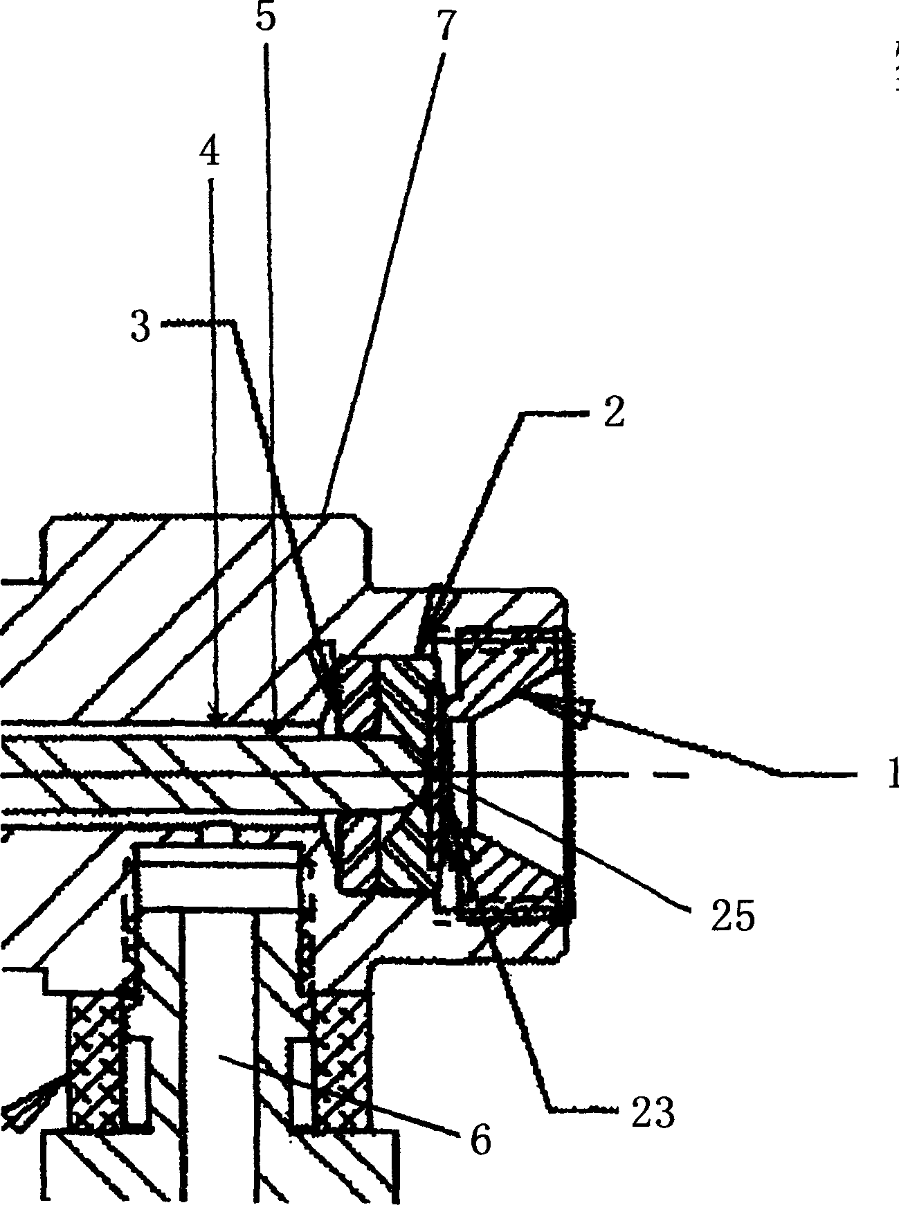
[0033] figure 1 A portion of an embodiment of an apparatus for treating exhaust gas by injecting an atomized substance into an exhaust gas stream is shown. The atomization (in this example an atomization of an aqueous urea solution) is sprayed via the valve spray nozzle 1 to an exhaust manifold (not shown). The atomization is produced in a pressure vortex atomizer 25 which rests against an adapter plate 23 in the valve seat 2 . The manifold (not shown) includes a catalytic converter for selective catalytic reduction of nitrogen oxides in the presence of aqueous urea aerosols.

[0034] Said liquid, in this example an aqueous urea solution, is supplied to the first chamber 4 via supply means 6 connected to the housing 7 . The figures show only one feeder, but multiple feeders are also conceivable. It is possible to inject liquids which are already mixtures into the first chamber, but the invention also contemplates introducing multiple liquids into the chamber in order to ach...


PUM


Abstract

A device for injecting at intermittent periods a dispersion of a liquid at controlled pulsing periods into exhaust fumes of a combustion engine, said liquid contains a component which reacts with a component of the exhaust fumes at a catalytic converter, said device comprises a housing containing a first chamber a means for supplying the liquid into a first chamber a means for pumping the liquid from the first chamber into a pressure swirl atomizer where the liquid is dispersed, said swirl atomizer comprising an outlet nozzle leading the dispersion into an exhaust manifold through which the exhaust fumes are directed prior to being converted at the catalytic converter, said device further comprises a means for controlling the means for pumping such that a pulsing period during which the liquid is injected into the swirl atomizer is controlled to be from about 1 to about 1000 milliseconds as well as a method for injecting a dispersion of a liquid into exhaust fumes of combustion engines.

Description

technical field [0001] The invention relates to an injection device for injecting an atomized active component into exhaust gas, in particular from an internal combustion engine, especially a diesel engine, for the catalytic reduction of harmful components in the exhaust gas, in particular nitrogen oxides. Background technique [0002] There is an increasing demand for a significant reduction of nitrogen oxide emissions from internal combustion engines, especially diesel internal combustion engines, in motor vehicles such as trucks, buses and motorcycles. The nitrogen oxide content in the exhaust gas can be reduced by selective catalytic reduction (SCR), in which the exhaust gas is guided into a catalytic converter together with an aqueous urea solution. At this converter, the catalytic nitrogen oxides react with the urea solution to reduce the toxic compound. For the most efficient conversion, fine atomization of the aqueous urea solution in the exhaust gas is required. T...

Claims


Application Information

Patent Timeline
Patent Type & Authority Applications(China)
IPC IPC(8): F01N3/20B01D53/94B01D53/79B60K13/04
CPCF01N2610/02F01N2610/1453B01D53/9431F01N2610/1433F02M61/1853Y02T10/24B01D2251/2067F01N3/2066B05B1/3436B01D53/90F01N2610/146F01N3/208B05B9/0403F02M61/162F01N2900/0422Y02A50/20Y02T10/12
Inventor 杰弗里·斯科特·约翰逊克利福德·P·科瓦尔迪特尔·迈施马蒂亚斯·布勒克
Owner CUMMINS LTD
Why Eureka
Try Eureka