Impeller of power device utilizing wind energy

A power device and blade technology, which is applied in the blade field of wind energy utilization power device, can solve the problems of increasing the load of the fan, the weight of the wind wheel, the increase of the weight of the blade, and the inability to effectively improve the efficiency of the fan, etc.

Inactive Publication Date: 2006-10-04
FLY RENEWABLE ENERGY TECH
View PDF0 Cites 2 Cited by
  • Summary
  • Abstract
  • Description
  • Claims
  • Application Information

AI Technical Summary

Problems solved by technology

Although the purpose of increasing the solidity of the blade can be achieved by increasing the width of a single blade, aerodynamics requires that the thickness of the lift-type blade must also be increased accordingly, r

Method used


Image

  • Impeller of power device utilizing wind energy
  • Impeller of power device utilizing wind energy
  • Impeller of power device utilizing wind energy

Examples


Embodiment Construction

[0022] The present invention will be further described below in conjunction with the accompanying drawings and embodiments.

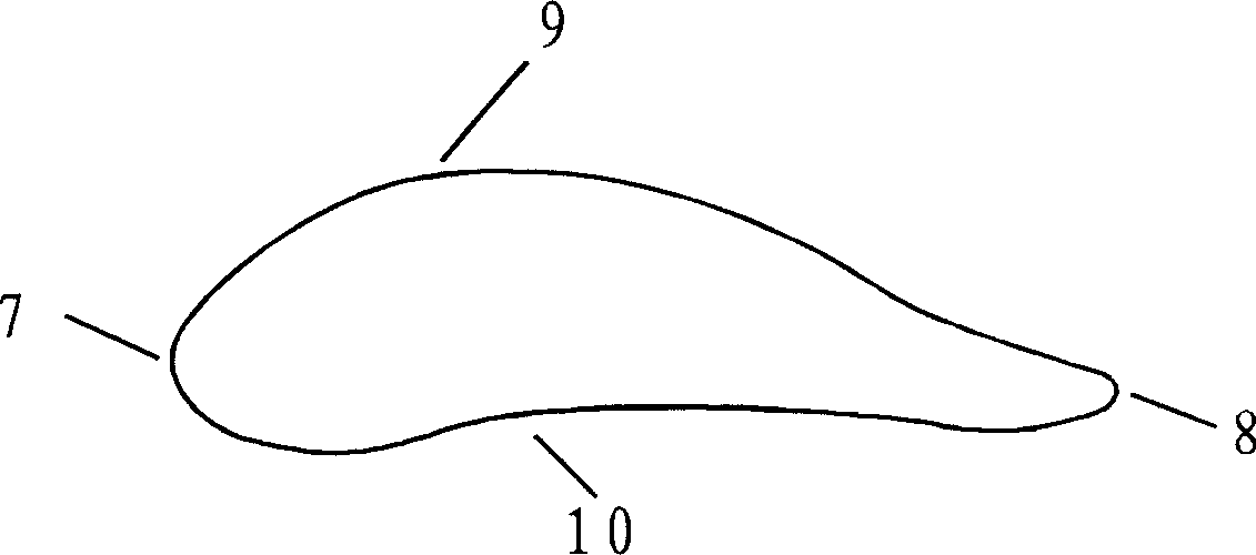
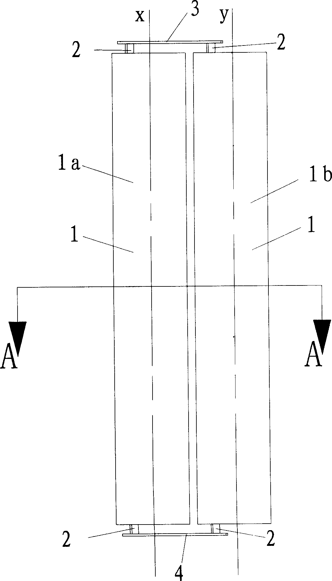
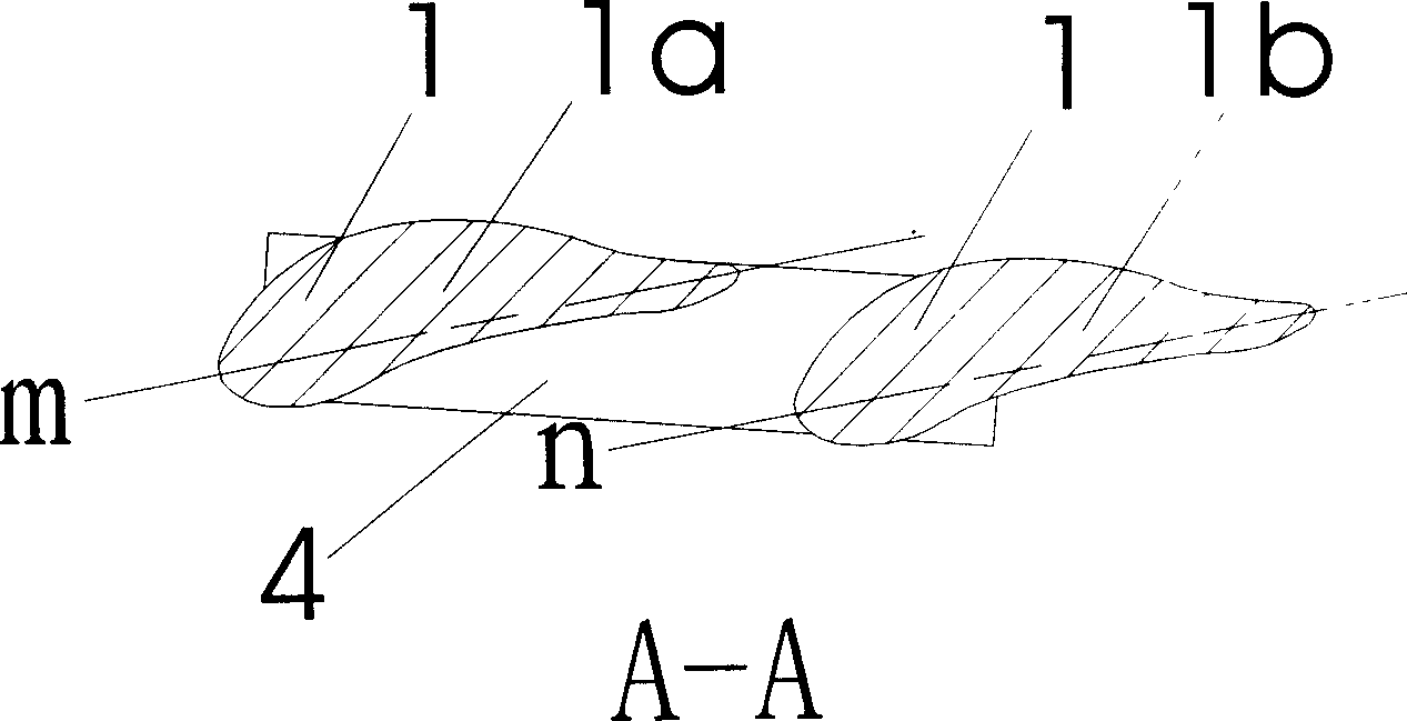
[0023] Depend on figure 1 , figure 2 , image 3 It can be seen that the blade of a wind energy power plant described in the present invention is composed of a first blade 1a, a second blade 1b, an upper beam 3 and a lower beam 4 to form a blade unit, and the abdomen 10 of the first blade 1a faces the second blade 1a. The back 9 of the second blade 1b, the heads 7 of the first blade 1a and the second blade 1b are in the same direction, one end of the first blade 1a and the second blade 1b is connected to the upper beam 3 through the connecting shaft 2, and the other end is connected through the connecting shaft 2 Connected to the lower beam 4, the distance between the horizontal axis m of the first blade 1a and the horizontal axis n of the second blade 1b is 0 to 10 times the thickness of the blade, and the included angle is 0 to 90 degrees. The verti...


PUM


Abstract

The invention discloses a blade of wind-energy dynamic device, which comprises at least two blades. The abdominal region of one blade of adjacent blades faces the back of the others and the heads of adjacent blades are at one direction. One end of blade connects the upper beam through the shaft and the other end connects the lower beam through the shaft. At least two blades and upper and lower beam constitute a blade unit. The invention can increase or enlarge elevating force of blade, which improves the wind-power utility efficiency.

Description

technical field [0001] The invention belongs to a blade of a wind energy utilization power device, in particular to a blade of a vertical axis wind energy utilization power device. technical background [0002] Because the ratio of the area of ​​the blades of the vertical axis fan in the sweeping surface to the sweeping area, that is, the solidity of the blades, is much smaller than that of the horizontal fan blades, this greatly affects the efficiency of the vertical axis fan. However, vertical shaft fans have great cost advantages in terms of design, manufacture, installation, and transportation, which makes it extremely important to improve the efficiency of vertical shaft fans. Although the purpose of increasing the solidity of the blade can be achieved by increasing the width of a single blade, aerodynamics requires that the thickness of the lift-type blade must also be increased accordingly, thus resulting in a multiplied increase in the weight of the blade. The disad...

Claims


Application Information

Patent Timeline
IPC IPC(8): F03D11/00F03D11/04F03D9/00F03D3/06
CPCY02E10/728Y02E10/74
Inventor 李锋王树全程钰庞兵卢建军
Owner FLY RENEWABLE ENERGY TECH
Why Eureka
Try Eureka