
Motion control apparatus and method, position instruction apparatus, position instruction method and control programme

A technology for controlling devices, moving vectors, applied in the field of photographic images, which can solve problems such as slow running

Inactive Publication Date: 2006-10-11
SEIKO EPSON CORP
View PDF0 Cites 36 Cited by
  • Summary
  • Abstract
  • Description
  • Claims
  • Application Information

AI Technical Summary

Problems solved by technology

In this way, it is necessary to perform slow movement while being aware of the relative relationship between the robot coordinate system and the camera coordinate system, causing a burden on the commander.

Method used


Image

  • Motion control apparatus and method, position instruction apparatus, position instruction method and control programme
  • Motion control apparatus and method, position instruction apparatus, position instruction method and control programme
  • Motion control apparatus and method, position instruction apparatus, position instruction method and control programme

Examples


Embodiment Construction

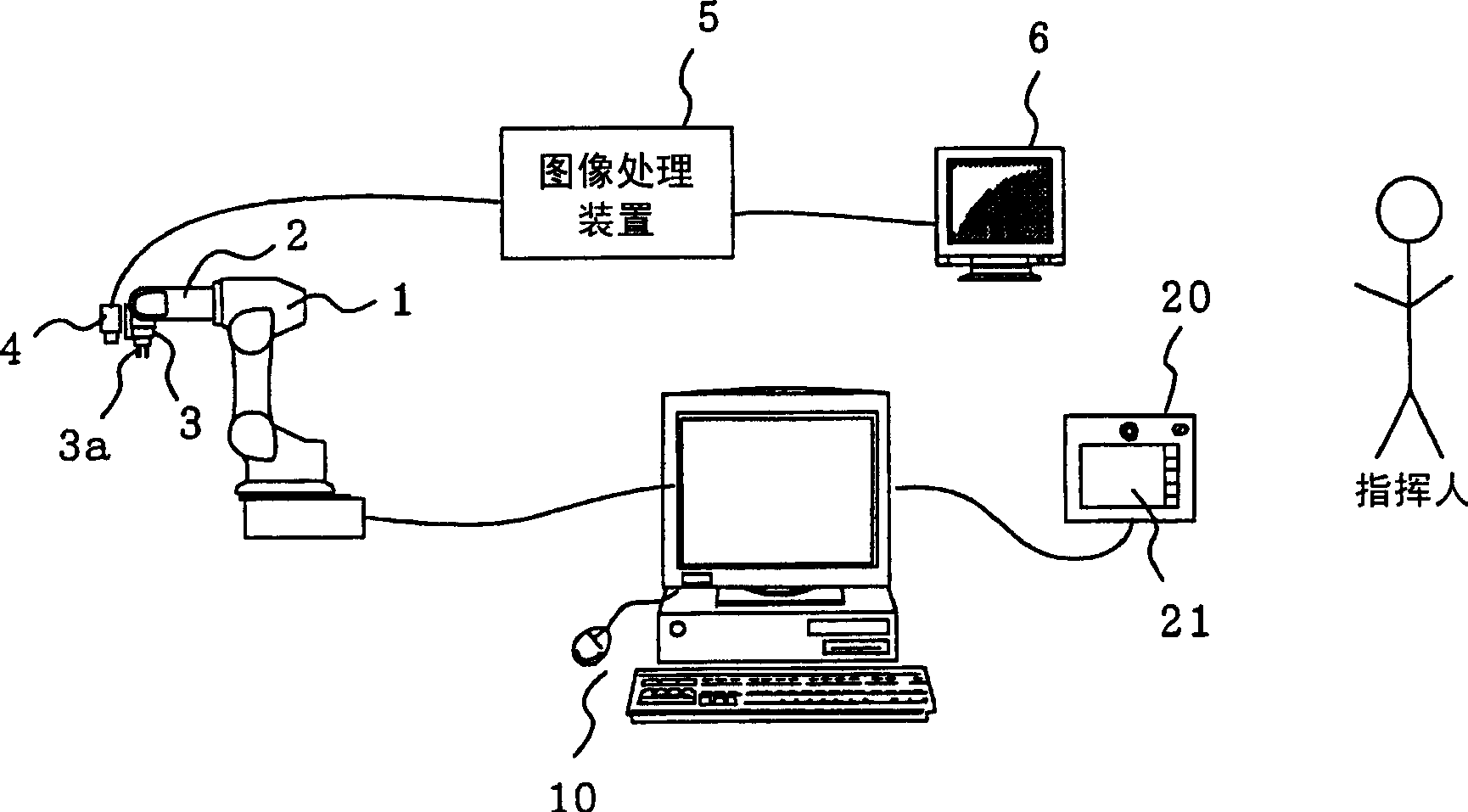
[0032] figure 1 It is a figure which shows the overall structure of the robot system to which the movement control apparatus for robot position command of embodiment of this invention is applied.

[0033] In this example, the robot 1 is composed of a multi-joint robot having a plurality of joints, and a robot finger 3 at the tip of an arm 2 is equipped with a working tool 3a capable of holding a workpiece and a camera 4 for imaging the workpiece. Images captured by camera 4 are processed by image processing device 5 and displayed on monitor 6 . In addition, the robot 1 , the robot control device 10 for controlling the robot 1 , the robot control device 10 , and the command operation device 20 for commanding and operating the robot 1 . All of these constitute a robot system.

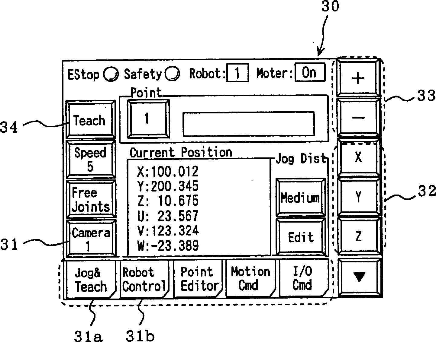
[0034] The command operation device 20 includes: image 3 and Figure 4As shown, a touch-panel display mechanism 21 that displays command images; a storage mechanism (not shown) that stores various i...


PUM


Abstract

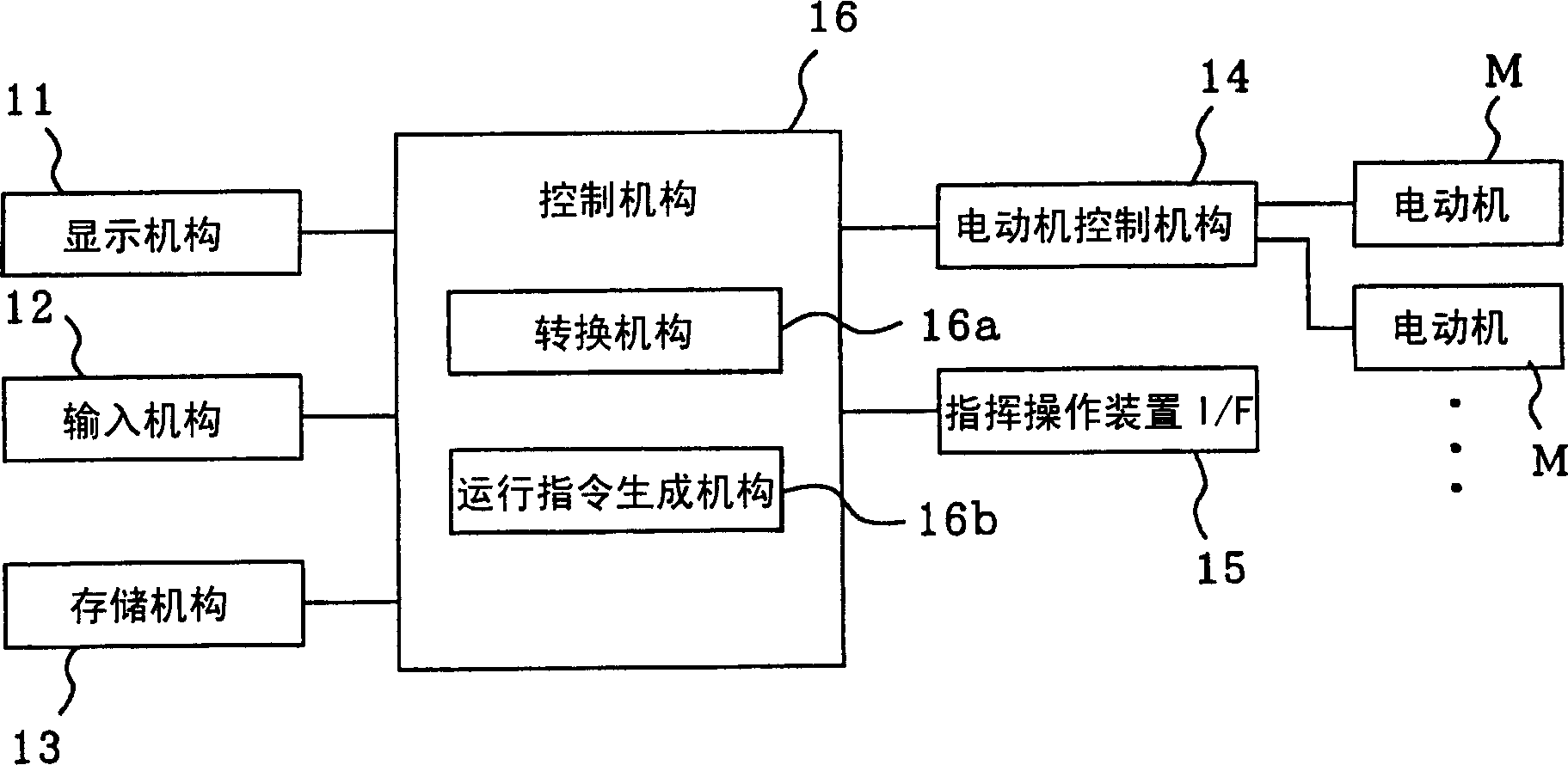
A motion control apparatus for teaching a robot position includes an operating unit that inputs an operating command to a robot on a camera coordinate system having, as a reference, an image capturing screen displayed on the monitor, a converting unit that generates a motion vector on the camera coordinate system for moving the robot from the current position to the next moving position in accordance with the operating command on the camera coordinate system input from the operating unit and converts the motion vector on the camera coordinate system into a motion vector on a robot coordinate system, an operating-instruction generating unit that generates a motor instructing value to be given to a motor arranged at a joint of the robot 1 based on the motion vector on the robot coordinate system obtained by the converting unit, and a motor control unit that controls the motor arranged at the joint of the robot in accordance with the motor instructing value generated by the operating-instruction generating unit.

Description

technical field [0001] The present invention relates to a technique suitable for operating a robot to a commanded predetermined position while observing photographed images captured by a camera. Background technique [0002] In a conventional inspection device, as a position command method for a robot, a camera is equipped on the robot, the object to be inspected is photographed by the camera, the captured image is image-processed by an image processing device, and the object to be inspected is inspected, and the image is It is displayed on the image display device. In this inspection device, before commanding the robot, the coordinate system of the robot is set in the image processing device. During the command, the position of the robot is transmitted from the robot controller to the image processing device. In this method, the robot coordinate system corresponding to the change of the robot posture is calculated, and the robot coordinate system whose display direction is ...

Claims


Application Information

Patent Timeline
Patent Type & Authority Applications(China)
IPC IPC(8): B25J9/22G05B19/42
CPCB25J9/1697G05B19/425G05B2219/39057G05B2219/39442G05B2219/40003G05B2219/40523B25J9/10B25J9/16B25J13/00
Inventor 说田信之
Owner SEIKO EPSON CORP
Learn More