Electric nail clippers

A nail clipper and electric technology, applied in manicure or pedicure tools, clothing, applications, etc., can solve the problems of time-consuming and laborious, inconvenient operation, and inability to trim nails, so as to achieve convenient use, environmental sanitation, Simple operation effect

Inactive Publication Date: 2006-10-18
孙生华
View PDF0 Cites 7 Cited by
  • Summary
  • Abstract
  • Description
  • Claims
  • Application Information

AI Technical Summary

Problems solved by technology

[0002] The current nail clippers are composed of two metal sheets with blades connected together, a connecting shaft and a pressing sheet. When cutting nails, the lever principle is used for manual operation. Sometimes, you need to ask someone for help, and you can't trim your nails by yourself

Method used


Image

  • Electric nail clippers
  • Electric nail clippers
  • Electric nail clippers

Examples


Embodiment Construction

[0014] Below in conjunction with accompanying drawing and embodiment the present invention is further described,

[0015] Such as figure 1 , figure 2 shown.

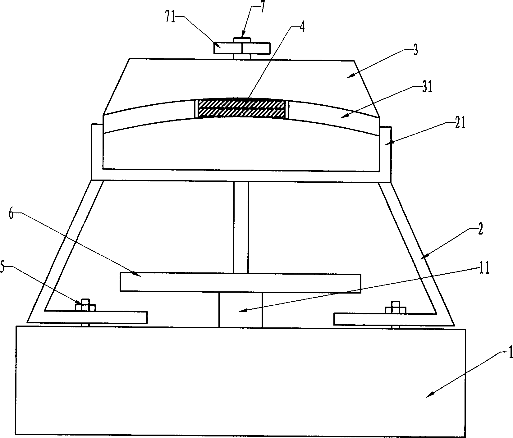
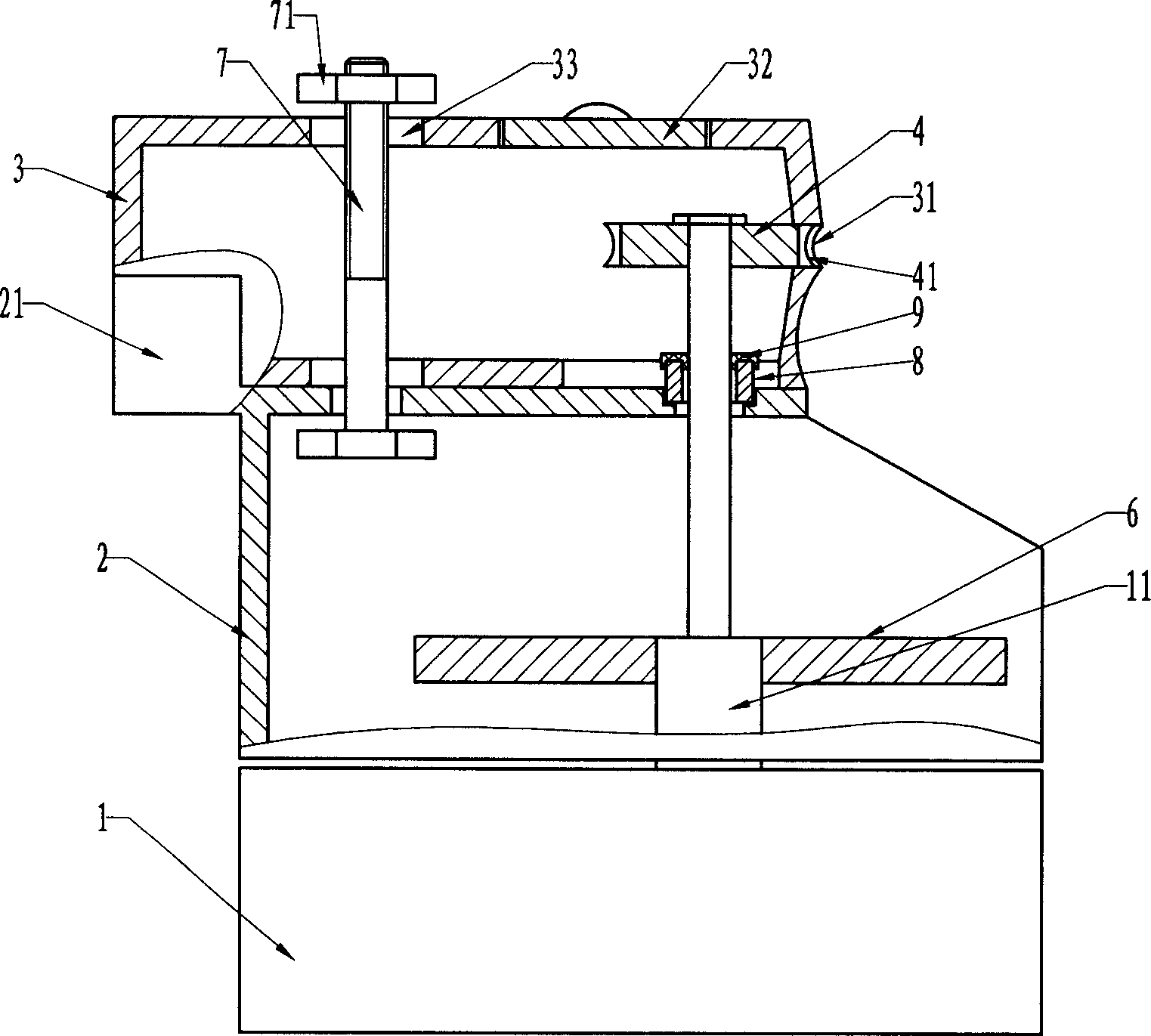
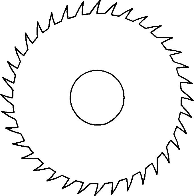
[0016] The electric nail clipper comprises a micromotor 1, a power supply, a bracket 2, a cover body 3 and a cutter wheel 4, the micromotor 1 is electrically connected to the power supply through a switch, the micromotor 1 is fixed on the bottom of the bracket 2 by a bolt 5, and the output shaft of the micromotor An inertial wheel 6 is installed on 11, and the top of support 2 is connected with cover body 3 by bolt 7, and micromotor output shaft 11 passes the bottom surface of cover body 3 and cutter wheel 4 is installed at the end, and the setting of inertial wheel 6 can guarantee The rotation speed of cutter wheel 4 is even; image 3 As shown, the side of the cutter wheel 4 is provided with some toothed blades 41, and the vertical section of the toothed blades 41 is arc-shaped, which is conducive to trimming the en...


PUM


Abstract

The electric nail clippers as household goods for trimming nails consists of micro motor connected to power source via a switch, rack and cutting wheel, and feature the micro motor fixed below the rack and with one inertial wheel mounted onto the output shaft, the rack with upper part connected to one hood, the hood with arched section in the shape corresponding to the end of nail, and the cutting wheel set in the opening of the arched section. The electric nail clippers are used for trim nails electrically and has simple operation and convenient use,

Description

technical field [0001] The invention relates to a nail clipper, in particular to an electric nail clipper, which belongs to daily necessities. Background technique [0002] The current nail clippers are composed of two metal sheets with blades connected together, a connecting shaft and a pressing sheet. When cutting nails, the lever principle is used for manual operation. Sometimes, you need to ask someone for help, and you can't trim your nails by yourself. Contents of the invention [0003] In order to solve the above-mentioned shortcomings in the prior art, the object of the present invention is to provide an electric nail clipper that saves time and effort and is easy to operate. [0004] The technical solution of the present invention is: an electric nail clipper, comprising a micro motor, a bracket and a cutter wheel, the micro motor is electrically connected to the power supply through a switch, and it is characterized in that: the micro motor is fixed under the su...

Claims


Application Information

Patent Timeline
Patent Type & Authority Applications(China)
IPC IPC(8): A45D29/02A45D29/05A45D29/14
Inventor 孙生华
Owner 孙生华
Why Eureka
Try Eureka