Dispenser having rotary actuator assembly

A dispenser and actuator technology, applied to engine components, valve operation/release devices, valve details, etc., to solve problems such as dispensing interruptions, dynamic seal wear, and loose seals

Inactive Publication Date: 2006-10-18
NORDSON CORP
View PDF1 Cites 23 Cited by
  • Summary
  • Abstract
  • Description
  • Claims
  • Application Information

AI Technical Summary

Problems solved by technology

On the other hand, if a looser dynamic seal is chosen, it will result in a leaky seal, allowing fluid to stick to the piston and compressed air to

Method used


Image

  • Dispenser having rotary actuator assembly
  • Dispenser having rotary actuator assembly
  • Dispenser having rotary actuator assembly

Examples


Embodiment Construction

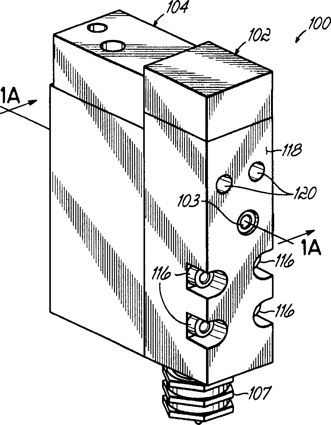
[0030] figure 1 is a schematic illustration of an example dispenser according to the invention. Unlike existing dispensers, the dispenser of the present invention includes a hydraulic section 102 and an actuating section 104 arranged side by side rather than vertically. Since the hydraulic section 102 is often connected to a heated manifold or other heated components, this side-by-side arrangement thermally isolates the actuating section 104 from such heated components. As a result, the O-rings and other seals in the actuating portion 104 are not exposed to high temperatures as in prior art dispensers. Also, other electrical components such as solenoids are not exposed to high temperatures. This allows the solenoid to be coupled closer to the actuating portion, reducing response time. Overall, this side-by-side arrangement will enhance reliability and performance relative to traditional vertically arranged dispensers.

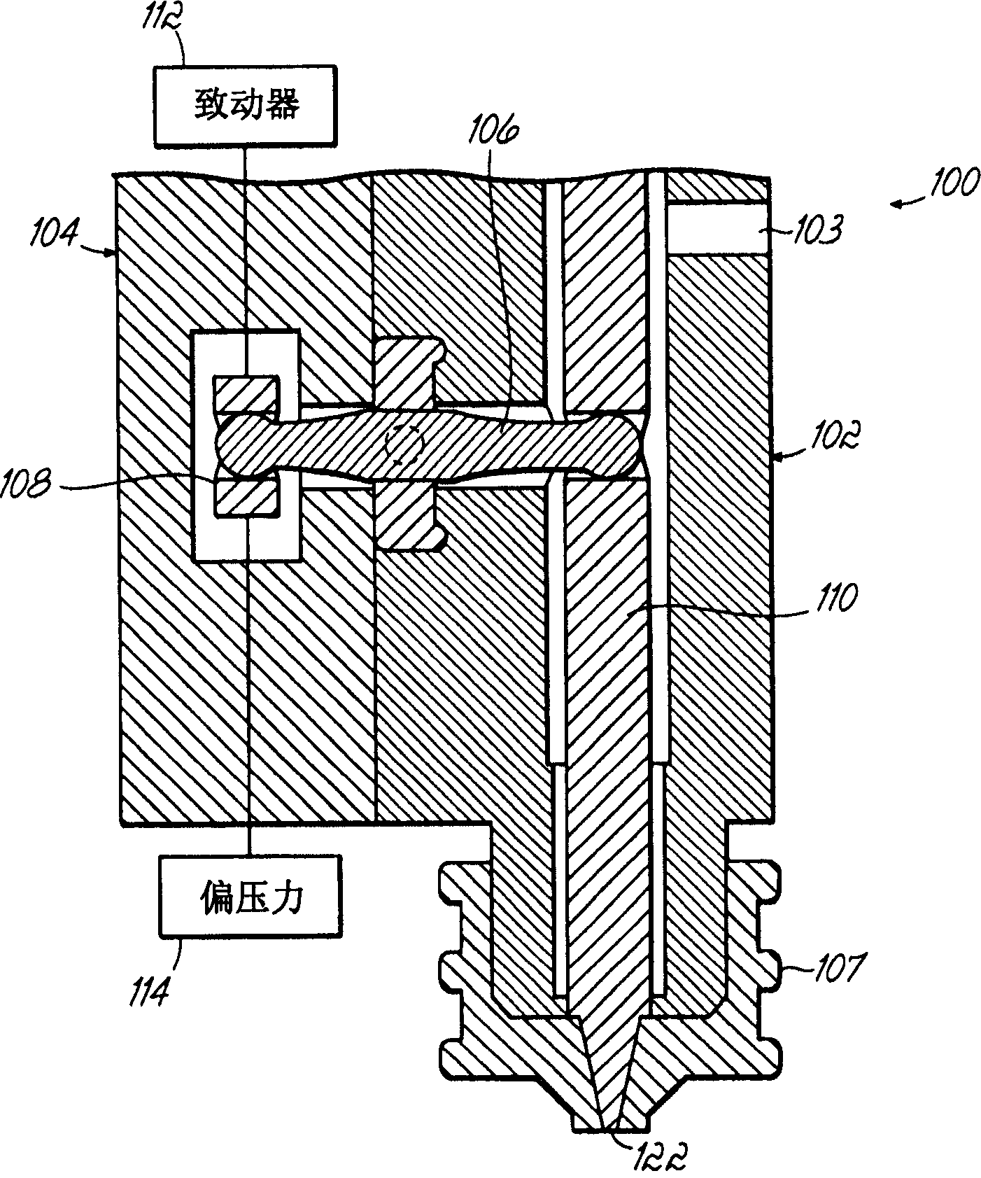
[0031] Such as Figure 1A , an example dispenser acc...


PUM


Abstract

A dispenser includes an actuating section having a first moveable member and a hydraulic section coupled with the actuating section and having a second moveable member. The hydraulic section is adapted to dispense a liquid from an outlet therein and the actuating section is adapted to control dispensing of the liquid. An actuator assembly operatively couples the first moveable member with the second moveable such that the first moveable member is operative to move the second moveable member between open and closed positions for respectively starting and stopping flow of liquid from the outlet. The actuator assembly may include a pivoting lever arm having a first end operatively coupled with the first moveable member, a second end operatively coupled with the second moveable member and defining a fixed pivot point therebetween.

Description

[0001] related application [0002] This application is a continuation of US Application Serial No. 10 / 975,227, filed October 28, 2004, the entire contents of which are hereby incorporated by reference. technical field [0003] The present invention generally relates to liquid dispensing devices for various purposes, especially for viscous liquids such as hot melt adhesives, sealants, paints and the like. Such devices are also known as fluid control valves, or dispensing guns or dispensing units. Background technique [0004] Typical dispensing devices for supplying liquids such as hot melt adhesive generally include a body with a valve stem for opening or closing a dispensing orifice. Generally, the valve stem is actuated in at least one direction by compressed air to dispense discrete quantities of compressed fluid. Either a spring mechanism or compressed air can be used to move the valve stem in the opposite direction to the valve seat. This prevents liquid from flowin...

Claims


Application Information

Patent Timeline
IPC IPC(8): F16K1/00F16K31/122
Inventor 克利斯多弗·R·查斯蒂内约翰·M·赖尼劳伦斯·B·赛义德曼
Owner NORDSON CORP
Why Eureka
Try Eureka