Passive optical network system for realizing protection switching and protection switching method

A passive optical network and protection switching technology, applied in the field of optical communication, can solve the problems of fiber failure, ONU branch protection switching, high cost, etc., and achieve high survivability and reliability

Active Publication Date: 2006-10-18
BEIJING GW TECH +1
View PDF1 Cites 24 Cited by
  • Summary
  • Abstract
  • Description
  • Claims
  • Application Information

AI Technical Summary

Problems solved by technology

However, this protection switching method requires dual routing of branch optical cables, which requires each ONU to provide two sets of branch optical cables with different routes, and the cost is relatively high for the access network environment with a large number of user nodes.
And in the actual access network planning, the branch optical cable from the transfer box to the ONU is usually set as a single route. If it is applied in practice, the existing network must be modified on a large scale, and the cost is very high; otherwise, if only in the existing Adding a branch optical cable to the optical cable path between the ONU and the OLT will easily cause the two branch optical fibers of the ONU with protection requirements to fail at the same time, and the protection switching of the ONU branch cannot be truly realized.

Method used


Image

  • Passive optical network system for realizing protection switching and protection switching method
  • Passive optical network system for realizing protection switching and protection switching method
  • Passive optical network system for realizing protection switching and protection switching method

Examples


Embodiment Construction

[0035] The present invention will be further described in detail below in conjunction with the accompanying drawings and specific embodiments.

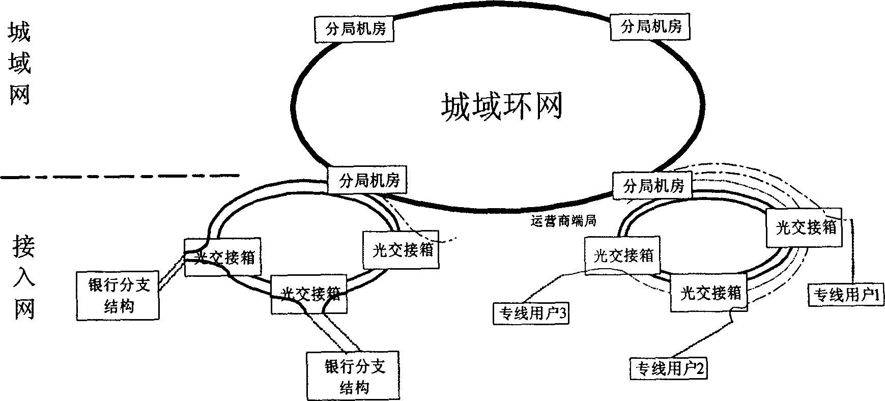
[0036] The passive optical network system and protection switching method for realizing protection switching of the present invention are applied to the optical network of "ring belt tree" network structure composed of ring network and tree branches connected thereto.

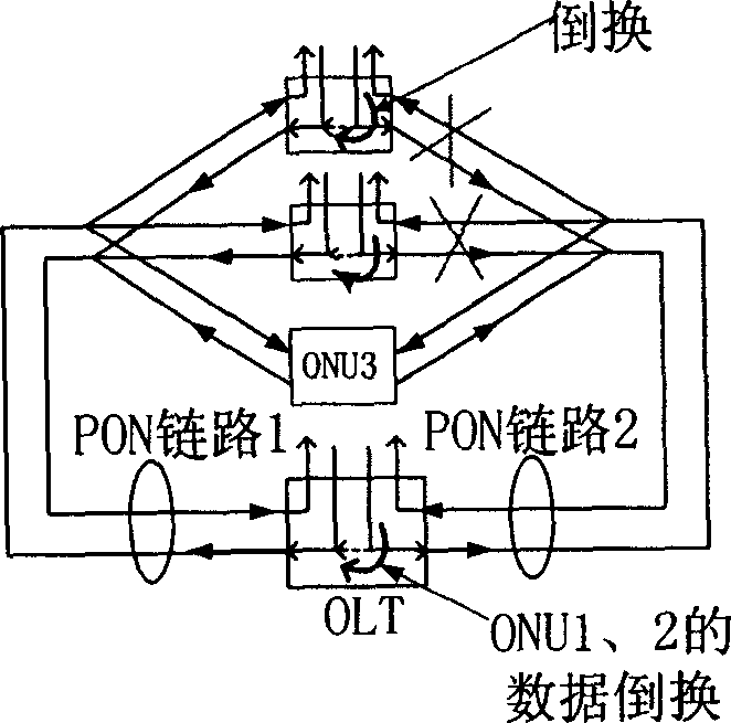
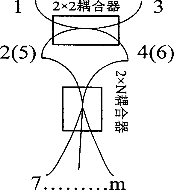
[0037] In the passive optical network system of the present invention, the OLT and the passive transfer node form a passive self-healing ring network through the optical fiber line, and the ONU is connected to the passive transfer node through the branch optical fiber to form a tree-shaped ONU branch. In the configuration of the node equipment, the OLT is equipped with two sets of optical transmission and optical reception modules; the ONU is equipped with one set of optical transmission and optical reception modules. And in order to block the interference of unwanted ...


PUM


Abstract

A passive optical network with protective switching over consists of ring network formed by OLT and passive mating node, ONU branch connected on mating node, two sets of light receiving / transmitting modules set in OLT, 2x2 coupler and 2x N coupler set in mating node. It is featured as connecting a pair port 1 and 3 of 2 x 2 coupler to said ring network and another pair port 2 and 4 to port 5 and 6 of 2 x N coupler, connecting the other N numbers of ports at 2 x N coupler to ONU, enabling to switching over two said sets from one set to another set when one is fault.

Description

technical field [0001] The invention relates to the technical field of optical communication, in particular to a passive optical network system capable of realizing protection switching and a protection switching method based on the system. Background technique [0002] At present, in the planning of urban access optical networks, the laying methods of optical cables generally used can be found in figure 1 As shown, the thick solid line in the figure indicates the optical cable on the metro ring network, the thin solid line indicates the optical cable connected to the backbone ring, the dotted line indicates the access chain optical cable, and the dotted line indicates the access branch optical cable. Install active sub-office computer rooms on the metropolitan area ring network, lay optical cables in a ring along the road from the sub-office computer room to the user direction, and place several passive optical transfer boxes along the way. Usually, the optical cables arra...

Claims


Application Information

Patent Timeline
Patent Type & Authority Applications(China)
IPC IPC(8): H04B1/74H04B10/032
Inventor 付晓松孙曙和邓羽刘冬赵晓蕴
Owner BEIJING GW TECH
Why Eureka
Try Eureka