
Friction lining plates

一种摩擦衬、摩擦片的技术,应用在摩擦衬片、摩擦离合器、制动盘等方向,能够解决费事等问题

Inactive Publication Date: 2006-10-18
ZF FRIEDRICHSHAFEN AG
View PDF2 Cites 19 Cited by
  • Summary
  • Abstract
  • Description
  • Claims
  • Application Information

AI Technical Summary

Problems solved by technology

From the processing technology point of view, the "reticulated groove" is stamped on the "pump groove", so it is relatively more laborious to manufacture such a friction lining

Method used


Image

  • Friction lining plates

Examples


Embodiment Construction

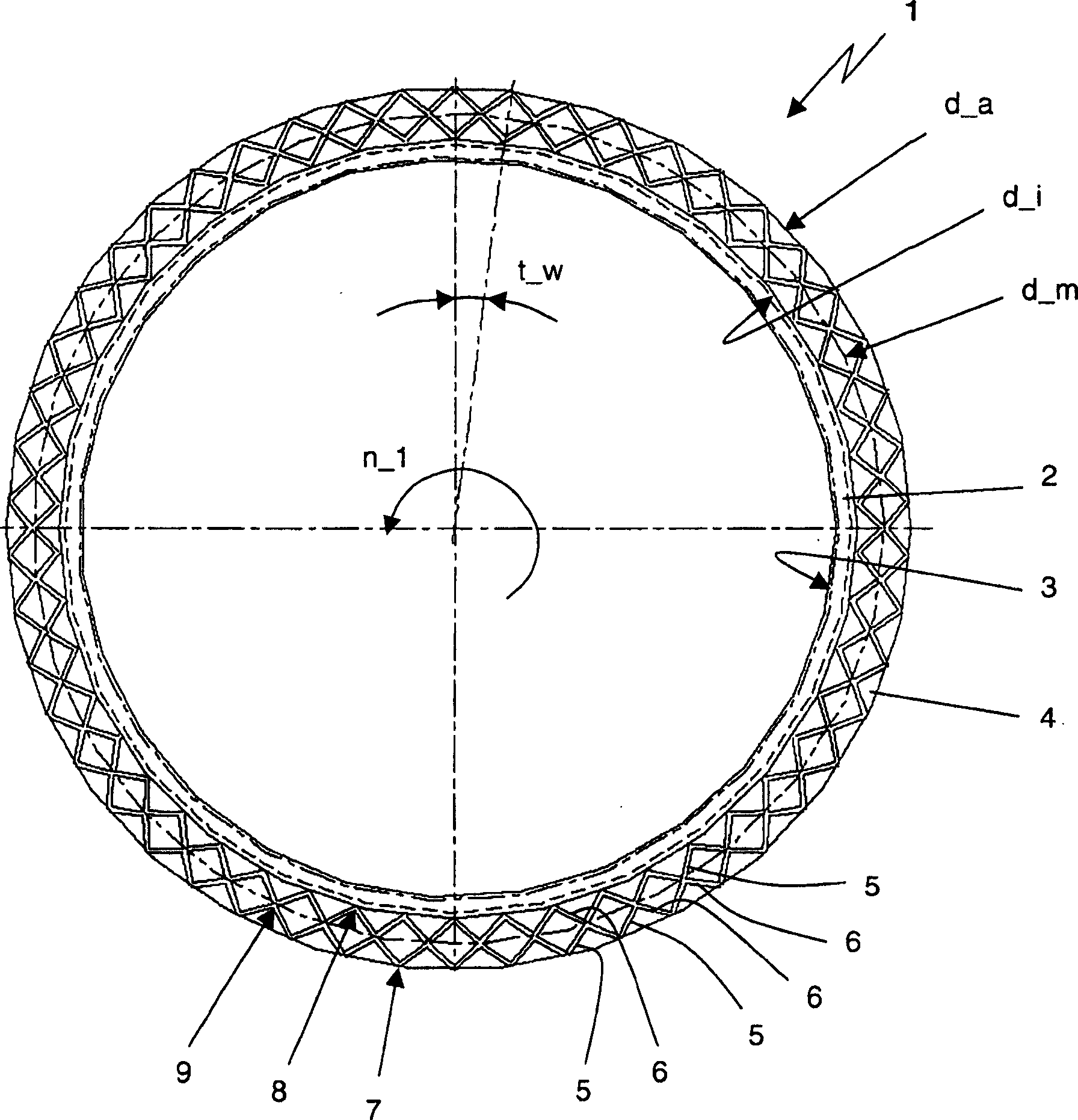
[0026] In the drawing, 1 designates a friction lining, for example in a sandwich construction, with an annular disk-shaped support plate 2 and a likewise annular disk-shaped friction lining, which is in the A flat end face of the carrier plate 2 is fixedly connected to the carrier plate, for example by means of adhesive bonding. The carrier plate 2 is made of steel, for example, and has a clamping contour 3 for a form-locking connection to a friction lining carrier (not shown here), which is located, for example, at the center of the carrier plate 2 . on the inside diameter. Of course, a corresponding clamping contour can also be provided on the outer diameter of the support plate in another configuration of the friction lining-friction lining.

[0027] The flat annular disk-shaped upper side of the friction lining forms the friction surface 4 for the friction engagement of the friction lining 1 and is geometrically defined by an outer diameter d_a and an inner diameter d_i. ...


PUM


Abstract

The invention relates to a friction lining (1) for a wet-running friction clutch element that rotates without a preferred direction of rotation in the assembled state, having at least one annular disc-shaped The contact friction surface (4) has grooves (5, 6) through which coolant can flow. The grooves (5, 6) form two groove groups superimposed on each other. The friction surface (4) has no groove edges oriented perpendicular to the direction of rotation. Each groove (5) of the first groove group acts as a through groove from the friction surface - inner diameter (d_i) to the friction surface - outer diameter (d_a) extension. Each groove (6) of the second groove group acts as a through groove from the friction surface - inner diameter (d_i) to the friction surface - outer diameter (d_a) extension. Each groove (6) of the second groove group intersects with a groove (5) of the first groove group in such a way that a groove intersection (8) lies on the friction surface-inner diameter (d_i), or a groove intersection (7) Located on the friction surface - outer diameter (d_a). Here, the total groove cross-sectional area on friction face-inner diameter (d_i) or friction face-outer diameter (d_a) is less than one between friction face-inner diameter (d_i) and friction face-outer diameter (d_a) Friction Surface - The total groove cross-sectional area in diameter.

Description

technical field [0001] The invention relates to a friction lining-friction lining for a wet-running friction clutch element, which has at least one annular disc-shaped friction surface for friction engagement, which has Coolant can flow through the grooves, wherein the grooves form two groove groups placed one above the other. Background technique [0002] A multi-plate clutch or multi-plate brake typically includes a plurality of annular friction plates. In this case, a first set of outer meshing disks is non-rotatably arranged in a friction lining carrier, and a second group of inner meshing disks is arranged non-rotatable on a wheel hub. Seen in the axial direction of the clutch element, the friction linings of the two sets engage one another in a meshing manner. In this case, the two groups are axially displaceable relative to each other and can be connected in pairs with a friction fit. [0003] Friction linings - The friction linings are generally designed in sandwi...

Claims


Application Information

Patent Timeline
Patent Type & Authority Applications(China)
IPC IPC(8): F16D65/12F16D13/64F16D55/00F16D69/00
CPCF16D2055/0058F16D2069/004F16D2200/0039F16D2200/0052F16D13/72F16D13/648F16D69/00F16D65/12F16D55/00F16D13/64
Inventor T·埃普勒J·贝克曼B·坎帕纳A·东格斯
Owner ZF FRIEDRICHSHAFEN AG
Learn More