Electrical connector

A technology of electrical connectors and sensors, applied in the direction of connections, inductors, circuits, etc., can solve problems such as connector arcing, connector pollution, abnormal equipment, etc., achieve effective electromagnetic coupling, reduce complexity, eliminate mechanical and The effect of the need for electrical connections

Inactive Publication Date: 2006-10-18
THALES HLDG UK
View PDF4 Cites 21 Cited by
  • Summary
  • Abstract
  • Description
  • Claims
  • Application Information

AI Technical Summary

Problems solved by technology

[0012] First of all, repeated turning on and off of any direct contact connector will inevitably cause wear and tear on the contact surface, especially if the connector has a high-power current passing through it when it is connected, it will cause arcing on the surface of the connector and oxidation
This can lead to performance degradation over time and can shorten the life of the connector or device and increase maintenance costs
[0013] Secondly, in these environments, when the connector is connected and disconnected, it is inevitable that some dirt, dust or water stains will pollute a certain part of the connector or the entire connector.
In simple direct contact conductive terminals, any dust and dirt on the contact surface will reduce the efficiency of the connector, resulting in abnormal, inefficient or inoperable equipment
Traditional connectors are not well suited to combat environments, especially when submerged in salt water, buried in sand or exposed to chemical warfare

Method used


Image

  • Electrical connector
  • Electrical connector
  • Electrical connector

Examples


Embodiment Construction

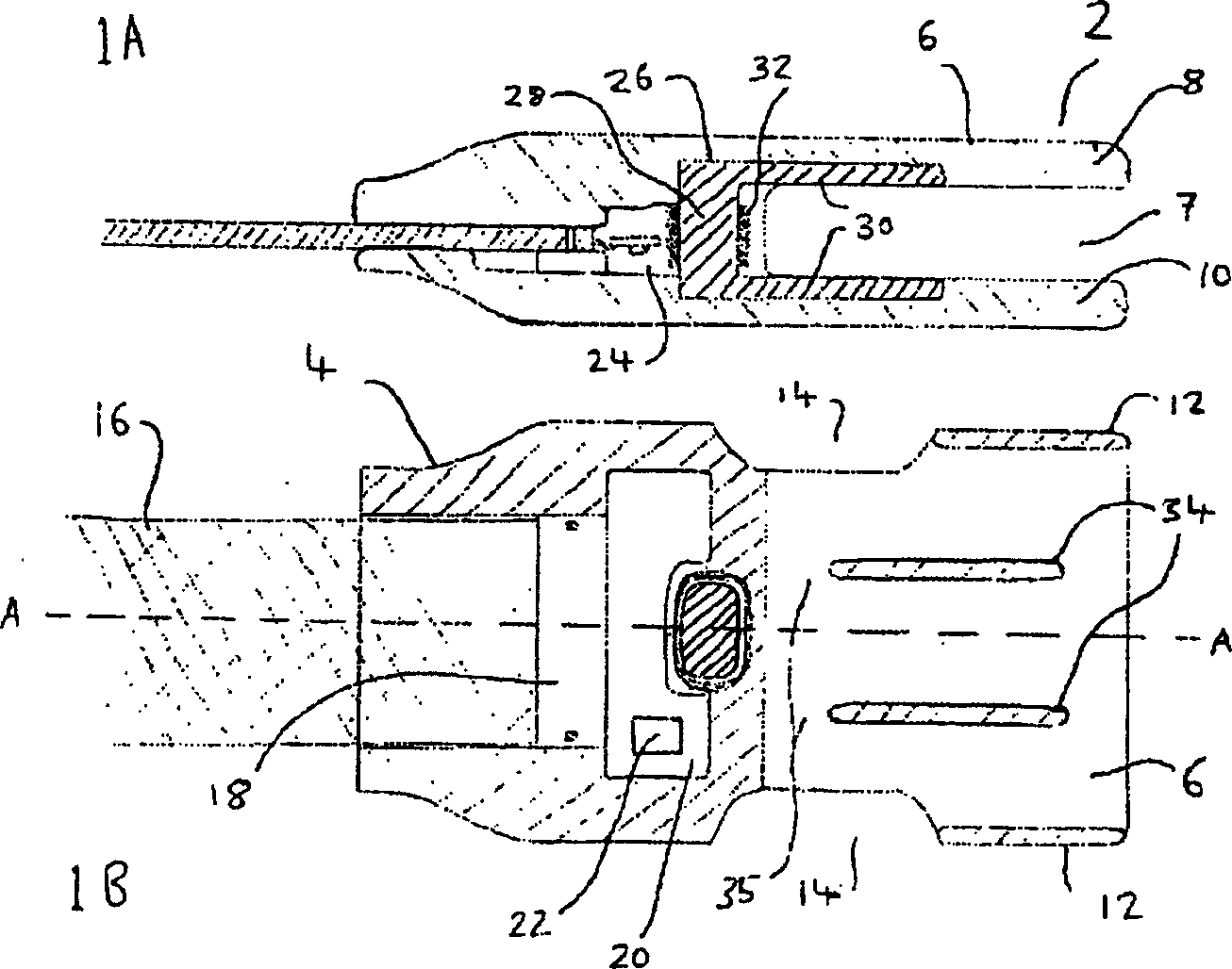
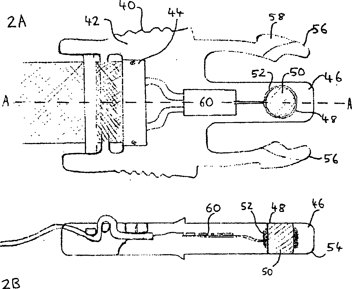
[0093] figure 1 A denotes the socket portion 2 of the non-contact connector of the present invention. The connectors have a structure similar to press-release clips or hooks generally found on rucksacks (see figure 2 Tongue 40 in . The socket part has a base 4 and a wall 6 extending from the bottom to define a socket 7 . The smooth curve of the slot portion makes it more comfortable for the user to use and carry. The socket walls include opposing upper walls 8 and lower walls 10 extending from the base, and two opposing walls 12 extending from the outlet of the socket to approximately the middle along the length of the socket. This arrangement provides a gap 14 between the base 4 and the side wall 12 on each side of the slot. These notches 14 act as pawls, and they cooperate with snap locks 56 at the tongue (see figure 2 ) work together. Such detents may also be provided, for example, by holes or openings in the socket walls, or by, for example, indentations or protrus...


PUM


Abstract

The present invention may provide a two-part electrical connector having a first part being a tongue portion having a base and a tongue extending longitudinally therefrom; a second part being a socket portion having a base and walls extending therefrom defining a socket for slidably receiving the tongue, the tongue portion and socket portion having locking means to permit releasable mutual engagement, said locking means including a locking member moveable between a first position in which the tongue is held in the socket and a second position in which the tongue is removable from the socket; a primary coupling element located in the tongue; and a secondary coupling element located in at least one of the socket walls, which elements provide a contact-less electromagnetic coupling when the tongue is engaged in the socket.

Description

technical field [0001] The present invention relates to connectors, in particular to contactless electrical connectors, ie connectors without direct contact between electrical conductors. Background technique [0002] The use of portable or handheld electrical equipment in harsh outdoor environments is becoming commonplace, especially for military use on the battlefield. It is desirable and sometimes necessary that such devices can be repeatedly connected and disconnected from a power source or other electronic devices for their own functional needs and for portability when not in use. [0003] Connectors commonly used in battlefield environments usually use direct contact plugs, and seals are used to protect the joints. Typical sealed connectors are circular and threaded. Examples are MIL-STD-1760 and MIL-STD-38999. [0004] As opposed to these direct contact plugs, the present invention relates to contactless connectors, particularly inductively coupled connectors, and a...

Claims


Application Information

Patent Timeline
Patent Type & Authority Applications(China)
IPC IPC(8): H01F38/14A41D1/00H01R12/24H01R13/52H01R13/58H01R13/627
CPCA41D1/002H01F38/14H01F2038/146H01R13/5219H01R13/5227H01R13/5833H01R13/6272H01R13/6273Y10S439/95H01R12/772H01G4/40
Inventor H·安德鲁
Owner THALES HLDG UK
Why Eureka
Try Eureka