Electricheating area control valve

A regional control, electric heating technology, applied in valve details, multi-port valves, valve devices, etc., can solve problems such as inability to satisfy users and inconvenient use.

Active Publication Date: 2006-10-25
谢庆俊
View PDF0 Cites 5 Cited by
  • Summary
  • Abstract
  • Description
  • Claims
  • Application Information

AI Technical Summary

Problems solved by technology

However, the currently used control valves need to be manually operated to control the regional

Method used


Image

  • Electricheating area control valve

Examples


Embodiment Construction

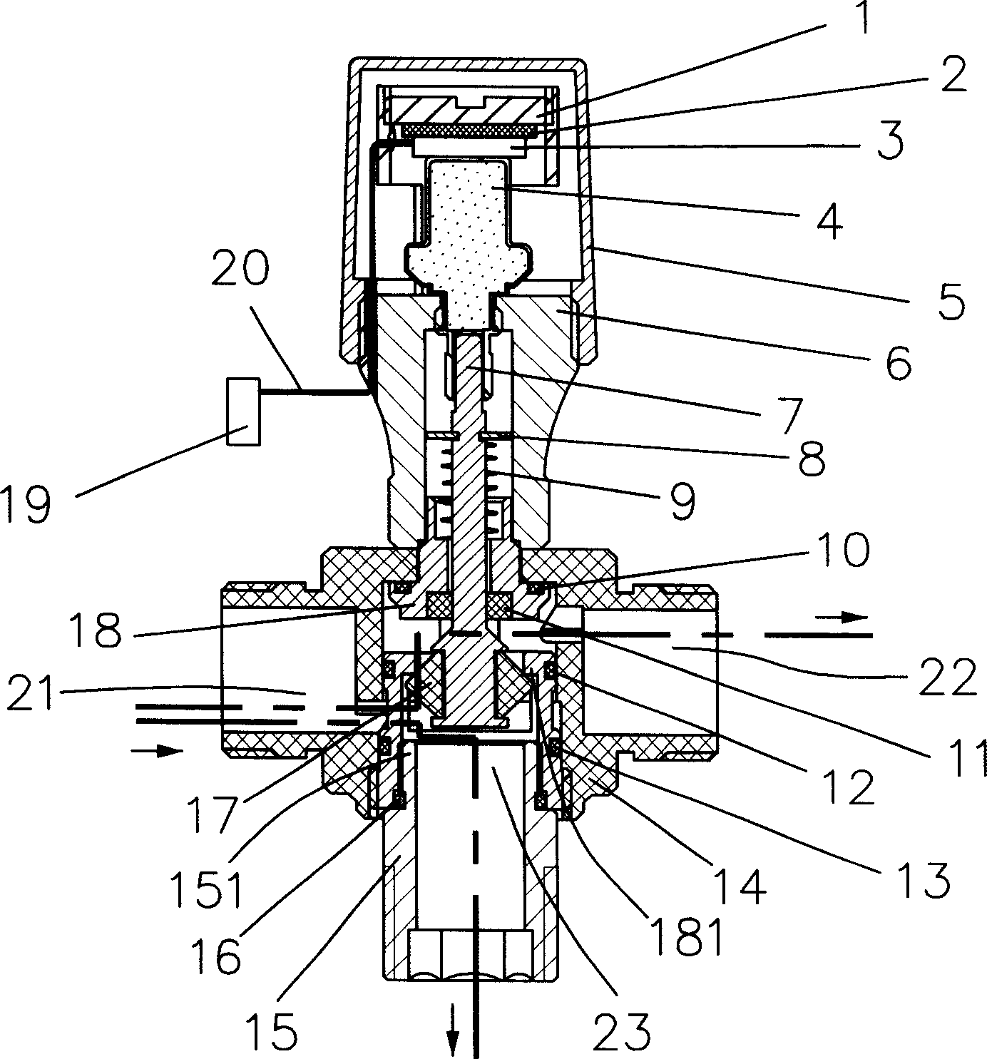
[0008] Please refer to the accompanying drawings, an electric control valve includes a compression screw 1, a heat shield 2, a thermal resistor 3, a thermal element 4, an outer cover 5, a connecting body 6, a valve stem 7, a collar 8, a spring 9, Sealing ring 10, sealing ring 11, sealing ring 12, sealing ring 13, valve body 14, joint 15, sealing ring 16, double-sided sealing ring 17, reversing valve body 18, thermostat assembly 19 and power cord 20.

[0009] The structure of each component and the connection relationship between the components will be described in detail below in conjunction with the accompanying drawings. As shown in the drawings, the outer cover 5 is installed on the upper part of the electric heating area control valve, the connecting body 6 is installed under the outer cover 5, the reversing valve body 18 is installed under the connecting body 6, and the joint 15 is installed under the reversing valve body 18. , The valve body 14 is installed outside the r...


PUM


Abstract

The invention discloses electric heating area control valve. It includes valve body, valve rod, hot resistance, thermal sensor, spring, outer cover, union body, reversing valve body, double sided seal ring, and thermostat package. The reversing valve body is set in the valve body. And its upper end is set joint. Its lower end is set the union body. The limited inner chamber of the outer cover, union body, and reversing valve body is set the hot resistance, thermal sensor, valve rod and spring. The valve rod is set the double sided seal ring. The thermostat package is connected with hot resistance electrical property. The invention can automatically control area flow quantity to adjust the temperature.

Description

【Technical field】 [0001] The invention relates to a control valve, in particular to an electric heating area control valve for automatic temperature control of heating and cooling systems. 【Background technique】 [0002] With the improvement of people's living standards, district heating and cooling methods have been used more and more. The heating and cooling system controls the regional flow through the opening and closing of the control valve, so as to achieve the purpose of regional temperature regulation. However, the currently used control valves need to be manually operated to control the regional flow, which is not convenient enough to use and cannot meet the requirements of users gradually. 【Content of invention】 [0003] The object of the present invention is to provide an electric heating area control valve, which can automatically control the flow in the area where it is located, and then achieve the purpose of automatic temperature adjustment. [0004] In or...

Claims


Application Information

Patent Timeline
IPC IPC(8): F16K11/02F16K31/64
Inventor 谢庆俊
Owner 谢庆俊
Why Eureka
Try Eureka