Embedded system buffer internal memory distribution method

An embedded system, memory allocation technology, applied in the direction of memory address/allocation/relocation, multiprogramming device, etc., can solve problems affecting program efficiency, etc., to achieve the effect of improving efficiency

Inactive Publication Date: 2006-10-25
ZHEJIANG UNIV
View PDF0 Cites 13 Cited by
  • Summary
  • Abstract
  • Description
  • Claims
  • Application Information

AI Technical Summary

Problems solved by technology

The disadvantage of dynamic allocation is that too

Method used


Image

  • Embedded system buffer internal memory distribution method

Examples


Embodiment Construction

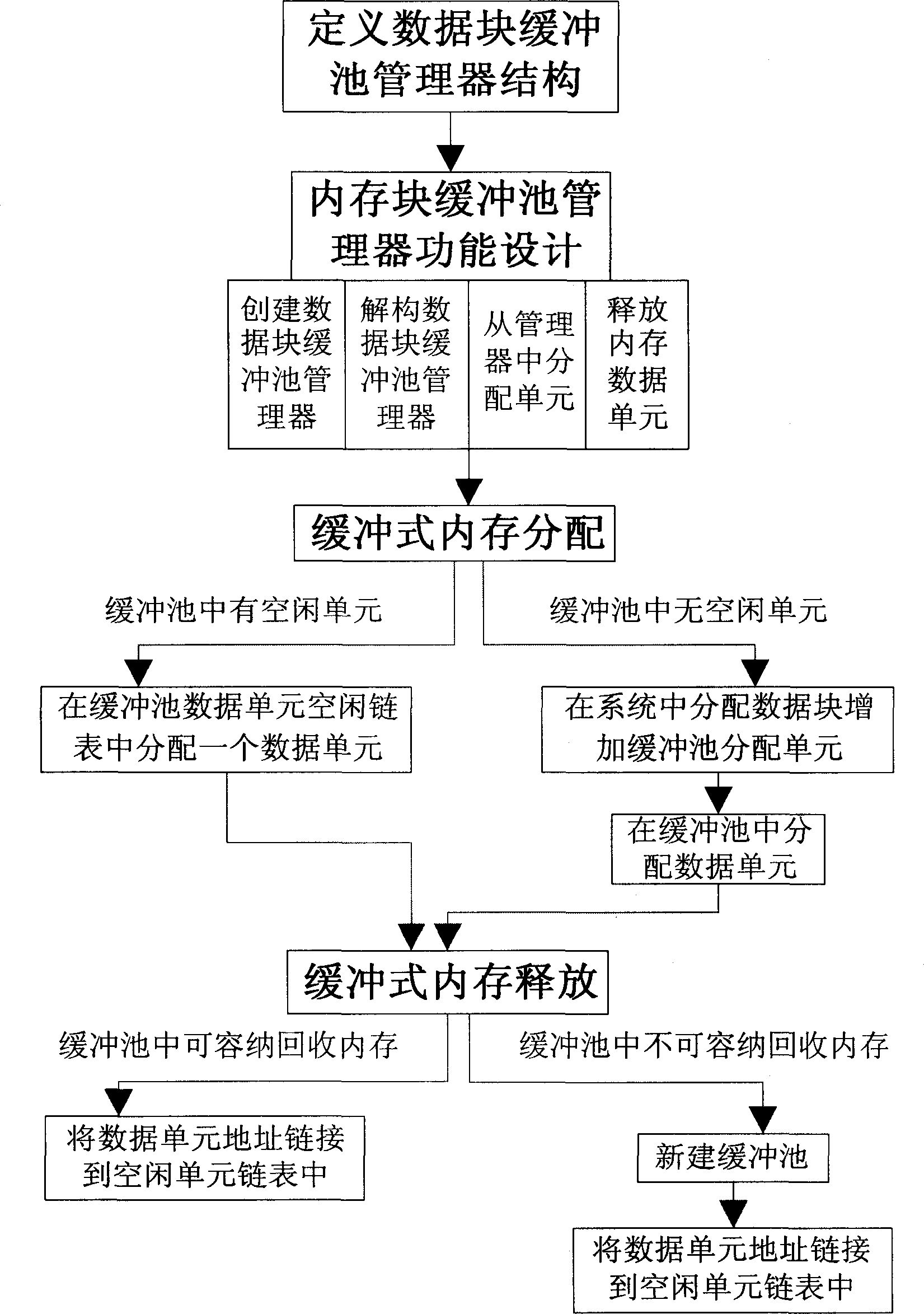
[0027] The content of the present invention will be described in detail below with reference to the drawings and specific embodiments. When implementing the buffered memory allocation method of an embedded system, the specific method is:

[0028] The first step: Define the structure of the data block buffer pool manager, including the content:

[0029] 1. Data unit size

[0030] The number of bytes of space occupied by a data unit in the memory, each data unit is the smallest unit of memory allocation;

[0031] 2. Data block size

[0032] The capacity of the unit data in the data block. Multiple data units are combined to form a data block. The size of the data block is fixed, so the number of data units in a block is also fixed;

[0033] 3. The maximum number of data blocks that can be accommodated

[0034] The maximum number of blocks in the buffer pool. If the data blocks in the buffer pool exceed the limit, another buffer pool will be opened;

[0035] 4. Number of used blocks ...


PUM


Abstract

Said method includes defining data block buffering pool data management unit structure, designing MB memory block buffer pool manager, buffer type memory allocation process and buffer memory releasing process. The present invention adopts embedded system buffer type memory allocation method, said method utilizing data block buffering pool posting distributed memory to data block buffering pool instead of immediately recovering system. Said invented method can directly use idleness data cell, until need to call system memory allocation, capable of avoid calling more operation system memory allocation and memory releasing, thereby raising system efficiency.

Description

Technical field [0001] The invention relates to the field of memory allocation strategies of an embedded system, in particular to a buffer memory allocation method of an embedded system. Background technique [0002] With the development of embedded systems, the research on the memory allocation mechanism of embedded systems is becoming more and more important. In many cases, the memory allocation mechanism is a key element that affects the efficiency of the program, so this aspect has always been the focus of research in the embedded field. Although there are many methods and related theories on the memory allocation mechanism, there are still many areas that need to be improved, and continuous research and exploration are needed. [0003] The memory allocation mechanism is an important and difficult problem in the research of embedded systems, because it must satisfy some characteristics, which are necessary for embedded systems, which is the difficulty. The following are the c...

Claims


Application Information

Patent Timeline
IPC IPC(8): G06F9/46G06F12/02
Inventor 陈天洲沙峰谢斌赵懿
Owner ZHEJIANG UNIV
Why Eureka
Try Eureka