Timer scheduling method

A scheduling method and timer technology, applied in multi-programming devices, digital transmission systems, electrical components, etc., can solve problems such as increased possibility, decreased timing accuracy of timers, system crashes, etc., to reduce excessive CPU consumption. possibility, avoid timing accuracy degradation, prevent system crash effect

Inactive Publication Date: 2006-10-25
HUAWEI TECH CO LTD
0 Cites 15 Cited by

AI-Extracted Technical Summary

Problems solved by technology

Therefore, the shortcoming of above-mentioned method is: the timeout processing of system is too much in one scheduling period, causes the central processing unit (CPU, Central Processing Unit) to be occupied for a long time and causes the timing accuracy of timer to decline, thereby affects the normal task scheduling of system, This further affects the timely processing of other services in the system. In particular, with the evolution of the modern communication system to the next-generation network, the maximum number of calls pr...

Abstract

This invention discloses a method for dispatching timers, which scans all timers with their accuracy smaller than the dispatch periods of two timers in each dispatch period and carries out overtime process to all overtime timers to scan all timers of the same kind with the accuracy greater than or equal to two dispatch periods and the same accuracy in n periods and carries out overtime process to the overtime timers in each period, in which, n is the integer greater than 1 and smaller than or equal to the entropy of the accuracy of the timer and its dispatch period, which carries out scan and overtime process to timers with the accuracy greater than or equal to the dispatch periods of two timers to reduce the possibility of processing large numbers of overtime timers in each dispatch period of a timer so as to reduce the cost of CPU.

Application Domain

Technology Topic

Image

  • Timer scheduling method
  • Timer scheduling method

Examples

  • Experimental program(1)

Example Embodiment

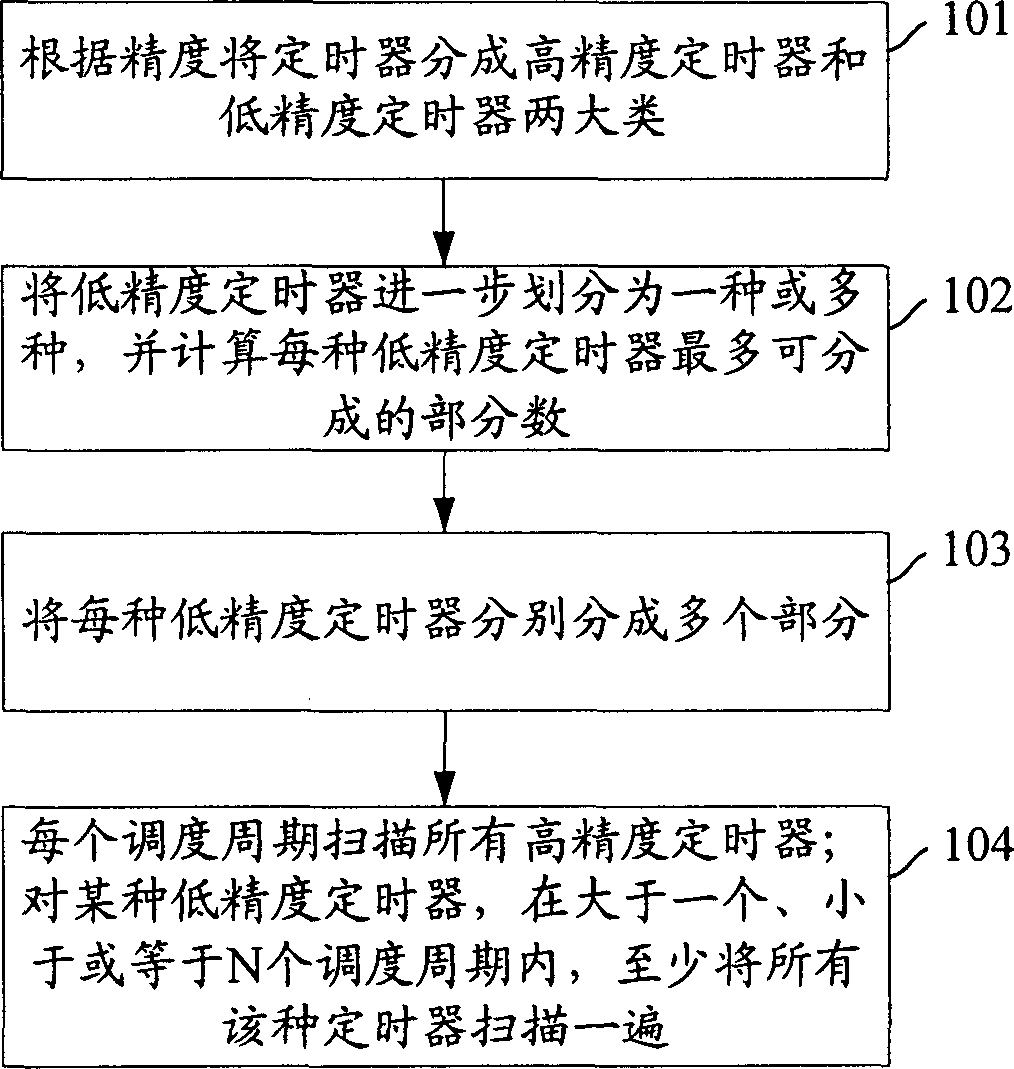
[0020] Although there may be a large number of timers in the system, the accuracy of these timers, that is, the timing duration, may be different. Moreover, timers with very high precision, such as 10 millisecond timers, account for a very small proportion. In modern communication systems, most timers are call-related timers, and their accuracy levels are usually 1 second or 100 milliseconds, that is, it is not necessary to scan these timers in every timer scheduling period. . For example, for a timer with an accuracy of 1 second, it only needs to be scanned once every 1 second.
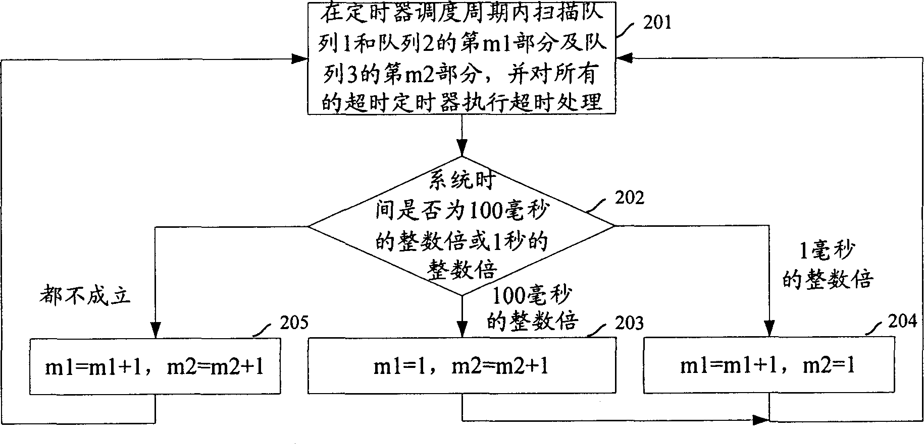
[0021] In view of the above situation, the core idea of ​​the timer scheduling method proposed by the present invention is: in each timer scheduling period, scan all timers whose accuracy is less than two timer scheduling periods, and perform timeout on all timeout timers. Processing; in n timer scheduling periods, scan all timers of the same type whose accuracy is greater than or equal to two timer scheduling periods and the same accuracy, and in each timer scheduling period, the timing that expires in the period is scanned The timer executes timeout processing, and n is an integer greater than 1, and less than or equal to the quotient of the precision of this type of timer and the timer scheduling period.
[0022] figure 1 Is the flow chart for implementing timer scheduling provided by the present invention, such as figure 1 As shown, the specific steps are as follows:
[0023] Step 101: According to the precision, the timers in the system are divided into two categories: high-precision timers, that is, timers whose precision is less than two timer scheduling periods; low-precision timers, that is, timers whose precision is greater than or equal to two. A timer scheduling period of the timer.
[0024] Since the timer scheduling period value must be less than or equal to the accuracy of the timer, the timers in the system are divided into two categories based on the timer scheduling period: high-precision timers and low-precision timers.
[0025] Step 102: Divide the low-precision timers into one or more types according to their accuracy, and calculate the maximum number of parts that can be divided into each type of low-precision timers.
[0026] All low-precision timers with the same precision are classified as the same kind of low-precision timers.
[0027] Let c be the precision of the timer and d be the timer scheduling period. For a certain low-precision timer, the maximum number of parts N that can be divided into is:
[0028] 1. c/d, when c/d is an integer;
[0029] 2. Round down the value of c/d, when c/d is not an integer.
[0030] Rounding down is relative to rounding up, that is, regardless of the value of c/d, the rounded value is equal to its integer part, for example: the value of 3.8 rounded down is 3, The rounded up value is 4.
[0031] Step 103: Divide each type of low-precision timer into multiple parts.
[0032] The number of parts that can be divided into different types of low-precision timers can be the same or different. For a certain low-precision timer, the number a that can be divided into parts meets the condition: a is an integer and 1
[0033] Step 104: In each timer scheduling period, scan all high-precision timers, and perform timeout processing on all time-out timers; for each type of low-precision timer, if it is greater than one timer scheduling period and less than or Equal to N timer scheduling periods, scan all timers with this accuracy at least once, and perform timeout processing on timers that time out in this period in each timer scheduling period. For example: for a certain precision low-precision timer, divide it into a part, and each timer scheduling period scans a part of the timer, then it only needs to be greater than or equal to a timer scheduling period and less than Or equal to N timer scheduling periods, select a timer scheduling period arbitrarily, select a part of the timer to scan in each period of the a timer scheduling period, and in each timer scheduling period The timeout process is performed on the timer that has timed out in this period. Of course, if the number m of selected timer scheduling periods is greater than a, then in each of the redundant m-a scheduling periods, one part of the timers can be selected to be scanned, or any timers can also be selected not to be scanned.
[0034] High-precision timers must be scanned within one timer scheduling period. The reason is that: the accuracy of high-precision timers is less than two timer scheduling periods. If the high-precision timers are scanned within more than or equal to two timer scheduling periods, Then, it is possible that some timers have timed out before being scanned. For example, if the timer scheduling period is 1 second, and the accuracy of a certain timer is 1.5 seconds, then all timers of this type must be scanned within 1 timer scheduling period.
[0035] The precision duration refers to the duration that is the same as the precision of the timer.
[0036] A specific embodiment is given below to further illustrate the present invention in detail.
[0037] Suppose a communication system contains three kinds of timers with precision, one is 10 milliseconds, and the time is the same as the timer scheduling period; one is 100 milliseconds; and the other is 1 second.
[0038] When using the timer scheduling method provided by the present invention to schedule these timers, it can be divided into two major steps, which are specifically as follows:
[0039] 1. First, divide all timers into two categories:
[0040] The first type: high-precision timers, that is, timers with an accuracy of 10 milliseconds, and all high-precision timers are formed into queue 1.
[0041]The second category: low-precision timers, that is, timers with an accuracy of 100 milliseconds and 1 second. Then, divide all low-precision timers with an accuracy of 100 milliseconds into n1 (1
[0042] Since 100 milliseconds/10 milliseconds = 10 and 1 second/10 milliseconds = 100, to ensure that the precision timer is scanned at least once within the precision duration of the low precision timer, it must be satisfied: for a timer with a precision of 100 milliseconds In other words, it can be divided into 10 parts at most; for a timer with an accuracy of 1 second, it can be divided into 100 parts at most. If the timers of 100 milliseconds and 10 seconds are divided into n3 (1
[0043] 2. Schedule timers according to the classification results, the specific steps are as follows figure 2 Shown:
[0044] Step 201: Scan all the timers in queue 1, and the m1 (1
[0045] Step 202: Determine whether the system time is an integer multiple of 100 milliseconds or whether the system time is an integer multiple of 1 second, if it is an integer multiple of 100 milliseconds, go to step 203; if it is an integer multiple of 1 second, go to step 204; if neither is true, Go to step 205.
[0046] Step 203: After setting m1=1 and m2=m2+1, return to step 201.
[0047] Step 204: After setting m1=m1+1, m2=1, return to step 201.
[0048] Step 205: After setting m1=m1+1, m2=m2+1, return to step 201.
[0049] by figure 2 It can be seen from the steps shown that, in each timer scheduling period, all high-precision timers, namely queue 1, are scanned, and all time-out high-precision timers are timed out; and for each low-precision timer , Each timer scheduling cycle only scans and processes a part of it. For low-precision timers of 100 milliseconds and 1 second, namely queue 2 and queue 3, the first timer scheduling scans queue 2 and queue 3. Part 1 performs timeout processing on the timeout timer, and the second timer scheduling scans the second part of queue 2 and queue 3 and performs timeout processing on the timeout timer,..., for queue 2 or queue 3 After all the timers have finished scanning and executing timeout processing, they restart from the first part of the queue, and so on. At the same time, it can be seen that the low-precision timer in the present invention may have multiple queues according to different precisions, and each queue is divided into multiple parts.
[0050] The above are only the process and method embodiments of the present invention, and are not intended to limit the present invention. Any modification, equivalent replacement, improvement, etc. made within the spirit and principle of the present invention shall be included in the present invention. Within the scope of protection.

PUM

no PUM

Description & Claims & Application Information

We can also present the details of the Description, Claims and Application information to help users get a comprehensive understanding of the technical details of the patent, such as background art, summary of invention, brief description of drawings, description of embodiments, and other original content. On the other hand, users can also determine the specific scope of protection of the technology through the list of claims; as well as understand the changes in the life cycle of the technology with the presentation of the patent timeline. Login to view more.

Similar technology patents

Boom stand

ActiveUS7207532B1Gradual and predictable variationReduce the possibilityPipe supportsStands/trestlesEngineeringCantilever
Owner:ROBERTS JEFFREY A +2

Classification and recommendation of technical efficacy words

Why Eureka
Try Eureka