Check patentability & draft patents in minutes with Patsnap Eureka AI!

Method of manufacturing an axially collapsible drive shaft assembly

A compressing flower, axial technology, applied in the direction of shafts, couplings, shafts and bearings, etc., can solve difficult, expensive and other problems

Inactive Publication Date: 2006-11-01
DANA CORP
View PDF2 Cites 4 Cited by
  • Summary
  • Abstract
  • Description
  • Claims
  • Application Information

AI Technical Summary

Problems solved by technology

However, it has been found to be more difficult and expensive to manufacture such axially compressible and / or extendable propshaft assemblies than conventional non-compressible propshafts

Method used


Image

  • Method of manufacturing an axially collapsible drive shaft assembly
  • Method of manufacturing an axially collapsible drive shaft assembly
  • Method of manufacturing an axially collapsible drive shaft assembly

Examples


Embodiment Construction

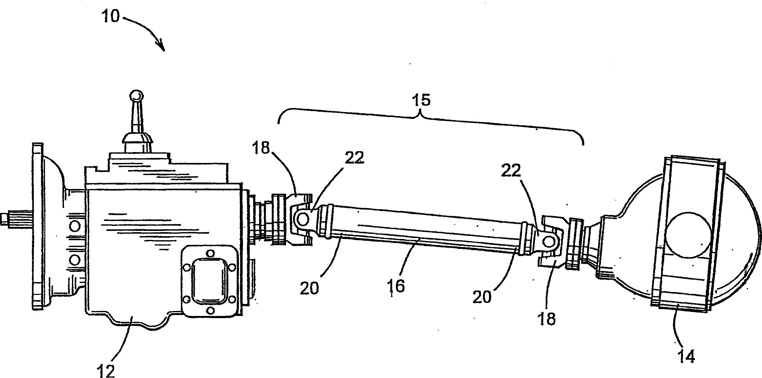
[0022] Referring now to the drawings, there is shown in FIG. 1 a conventional vehicle driveline of the prior art, indicated generally at 10 . A prior art driveline 10 includes a transmission 12 coupled to an axle assembly 14 via a driveshaft assembly 15 . The propshaft assembly 15 includes an elongated cylindrical propshaft tube 16 . As is typical in conventional vehicle drivelines 10 , the output shaft (not shown) of the transmission 12 and the input shaft (not shown) of the axle assembly 14 are not coaxially aligned. Accordingly, universal joints 18 are employed at each end 20 of propshaft tube 16 to rotatably connect propshaft tube 16 at an angle to the output shaft of transmission 12 and the input shaft of axle assembly 14 .

[0023] The connection between the end 20 of the propshaft tube 16 and the universal joint 18 is typically accomplished by a pair of end fittings 22, such as pipe yokes or slide yokes. The end 20 of the drive shaft tube 16 is open and adapted to rec...


PUM


Abstract

A method of manufacturing a driveshaft assembly that is axially collapsible includes the initial step of disposing a first hollow member about a forming mandrel having a cavity formed therein. The cavity includes a first radially inwardly extending portion having a first radial depth, and a second radially inwardly extending portion having a second radial depth. The second radially inwardly extending portion extends axially from the first radially inwardly extending portion. Then, the first hollow member is deformed into conformance with the cavity of the forming mandrel. A second hollow member is positioned relative to the deformed first hollow member and deformed into conformance with a deformed portion of the first hollow member. Such deformation may be by mechanical deformation, electromagnetic pulse forming, hydroforming, and the like. The first radially inwardly extending portion of the cavity forms a first spline in the first hollow member, and also forms a spline in the second hollow member. The second radially inwardly extending portion of the cavity forms a second spline in the first hollow member. Preferably, the first radial depth is greater than the second radial depth.

Description

technical field [0001] The present invention generally relates to a method of making an axially compressible spline assembly for transmitting power from a rotary power source to a rotatably driven mechanism. In particular, the present invention relates to an improved method for manufacturing axially compressible propshaft assemblies, such as those used in vehicle drivelines. Background technique [0002] Torque transmitting shafts are widely used to transmit rotational power from a source of rotational power to a mechanism that is rotatably driven. For example, in most land vehicles in use today, a transmission system is employed to transmit rotational power from the output shaft of the engine / transmission assembly to the input shaft of the axle assembly, thereby rotationally driving the wheels. To accomplish this process, conventional vehicle drivelines include hollow cylindrical propshaft tubes. The first universal joint is connected between the output shaft of the engin...

Claims


Application Information

Patent Timeline
IPC IPC(8): B21D53/00B21D26/02B21D26/14B21K1/12
CPCB60K17/22F16C3/03F16D3/06F16D2001/103F16D2250/00F16C2326/06
Inventor D·W·吉布森
Owner DANA CORP
Features
  • R&D
  • Intellectual Property
  • Life Sciences
  • Materials
  • Tech Scout
  • Unparalleled Data Quality
  • Higher Quality Content
  • 60% Fewer Hallucinations
Learn More