Check patentability & draft patents in minutes with Patsnap Eureka AI!

Driving synchronous rectifiers across the isolation barrier

A technology of synchronous rectifiers and transformers, which is applied in the directions of instruments, DC power input conversion to DC power output, and AC power input conversion to DC power output, etc., which can solve the problems of insufficient space for transformers and power supply size reduction, etc.

Inactive Publication Date: 2006-11-01
ASTEC INT LTD
View PDF0 Cites 1 Cited by
  • Summary
  • Abstract
  • Description
  • Claims
  • Application Information

AI Technical Summary

Problems solved by technology

[0003] As power supply sizes continue to decrease, there is often not enough room for a transformer with two secondary windings

Method used


Image

  • Driving synchronous rectifiers across the isolation barrier
  • Driving synchronous rectifiers across the isolation barrier

Examples


Embodiment Construction

[0011] The following description is only an example in terms of characteristics, without limiting the invention, its application or use.

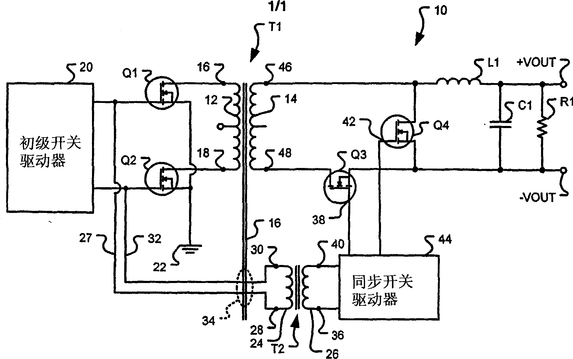
[0012] figure 1 One of various embodiments of switching power supply 10 is shown. The power supply 10 has a power transformer T1 , such as a planar or wirewound transformer with a primary coil 12 and a secondary coil 14 . Iron core 16 couples the magnetic flux between primary coil 12 and secondary coil 14 . In some embodiments, the power transformer T1 is a planar design. The first terminal 16 of the primary winding 12 is connected to the first primary switching transistor Q1. The second terminal 18 of the primary winding 12 is connected to the second primary switching transistor Q2. Both the gates of the switching transistor Q1 and the switching transistor Q2 are connected to the primary switch driver 20 as known in the art. Both the source of the first primary switching transistor Q1 and the source of the second primary switching tra...


PUM


Abstract

A switching power supply circuit has a power transformer having a core, a primary winding, and a secondary winding. A first switch has a control signal input and is connected to the primary winding of the power transformer. A synchronous rectifier has a control signal input and is connected to the secondary winding of the power transformer. A signal transformer has a primary winding and a secondary winding, and a first connection has a first end connected to the control signal input of the first switch and a second end connected to the primary winding of the signal transformer.

Description

technical field [0001] The present invention generally relates to a switching power supply with a synchronous rectifier, and in particular to a circuit for driving the synchronous rectifier. Background technique [0002] In the field of switching power supplies, it is well known to increase the efficiency of power supplies by using synchronous rectifiers and synchronous free-wheeling switches. The switching power supply usually has a transformer with one primary winding and two secondary windings. The first secondary coil provides power for rectification and load application. A second or auxiliary secondary coil provides signals for controlling the synchronous rectifiers and freewheeling switches. [0003] As the size of power supplies continues to decrease, there is often not enough room for a transformer with two secondary windings. In a power supply with a planar power transformer, the primary coil and main secondary coil occupy the width of the board, leaving minimal ...

Claims


Application Information

Patent Timeline
Patent Type & Authority Applications(China)
IPC IPC(8): H02M7/217H02M3/335
CPCH02M3/33592Y02B70/10
Inventor S·J·图马斯
Owner ASTEC INT LTD
Features
  • R&D
  • Intellectual Property
  • Life Sciences
  • Materials
  • Tech Scout
  • Unparalleled Data Quality
  • Higher Quality Content
  • 60% Fewer Hallucinations
Learn More