Method of error compensation in a coordinate measuring machine

A technology for measuring value and coordinate positioning, which is applied to measuring devices, mechanical measuring devices, instruments, etc., and can solve the problems of time-consuming and complicated calibration.

Inactive Publication Date: 2006-11-01
RENISHAW PLC
View PDF2 Cites 19 Cited by
  • Summary
  • Abstract
  • Description
  • Claims
  • Application Information

AI Technical Summary

Problems solved by technology

However, this articulated probe has the disadvantage of time-consuming calibration when in use
Moreover, the measurement system of the articulated probe installed on the existing coordinate measuring machine is a five-axis system, which makes the calibration more complicated

Method used


Image

  • Method of error compensation in a coordinate measuring machine
  • Method of error compensation in a coordinate measuring machine
  • Method of error compensation in a coordinate measuring machine

Examples


Embodiment Construction

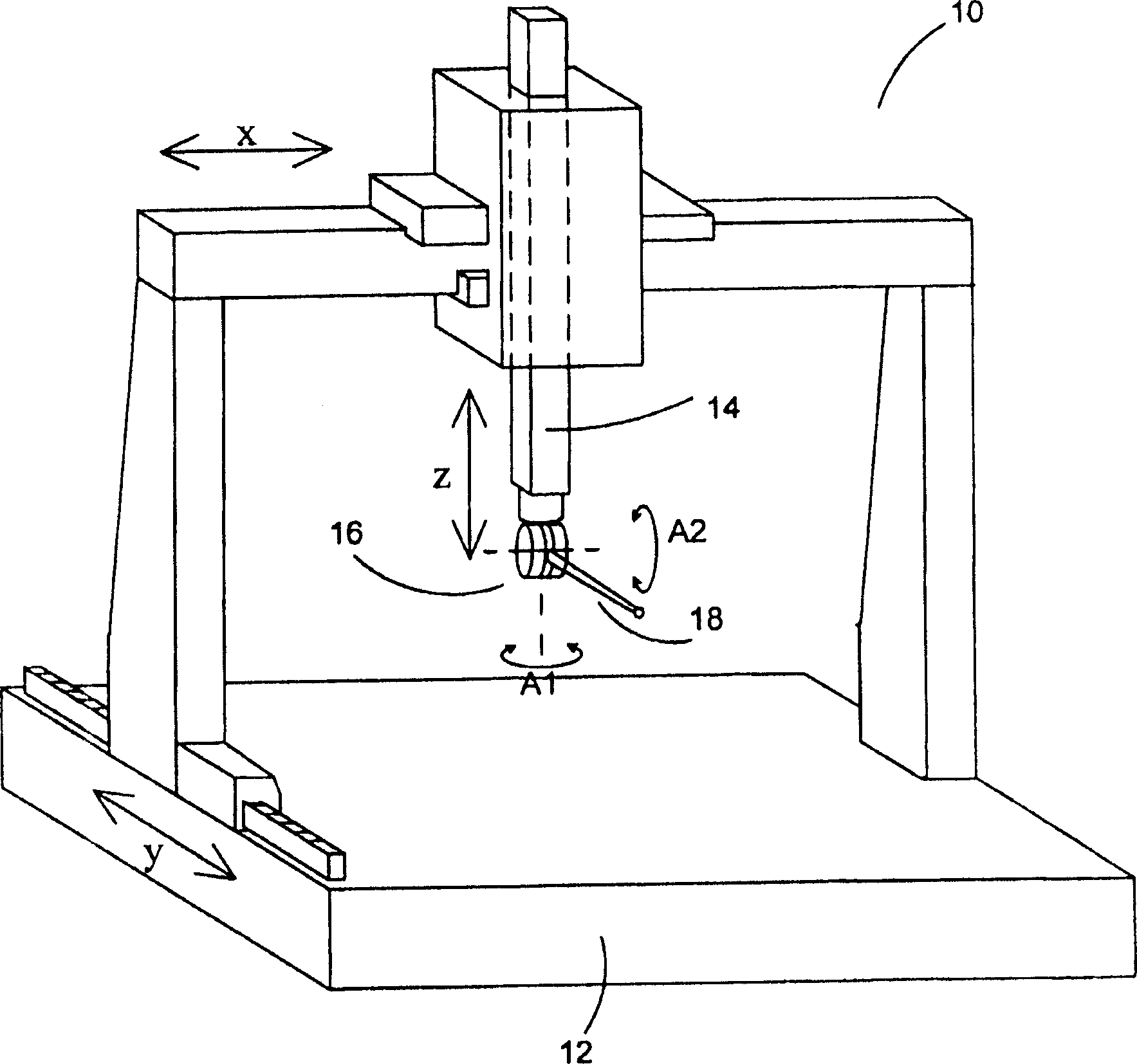
[0044] figure 1 Shown is the articulating probe mounted on a CMM. The coordinate measuring machine 10 includes a platform 12 on which a workpiece can be placed and an arm 14 movable in X, Y and Z directions relative to the platform 12 . An articulated probe 16 is mounted on the arm 14 of the coordinate measuring machine (CMM). The articulating probe head 16 allows a workpiece measurement probe 18 mounted thereon to rotate about two substantially perpendicular axes A1 and A2.

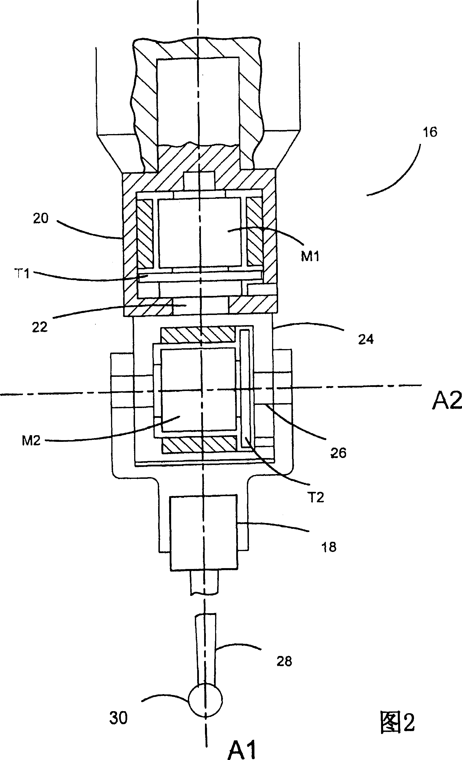
[0045]The robotic arm 14 is thus movable in the X, Y and Z directions by the X, Y and Z drives (not shown) of the CMM. Scale means (not shown) on X, Y and Z indicate the immediate coordinates of where the arm 14 is located. A rotary drive (not shown) located in the articulated probe enables movement of the probe around the two axes of rotation A1 and A2. This motion is measured by a rotary scale (not shown) located within the articulating probe 16 . The signal from the probe 18 indicative of deflect...


PUM


Abstract

A method of calibrating an articulating probe head comprising the steps of measuring an artefact of known dimensions with the workpiece sensing probe mounted on the articulating probe head, in which the articulating probe head is unlocked. An error functional map is generated corresponding to the difference between the measured and known dimensions of the artefact. Subsequent workpieces are measured with the articulating probe head unlocked and the corresponding correction applied. The true dimensions of the artefact may be determined by measuring it with a probe mounted on an articulating probe head in which the axes of the articulating probe head are locked. A mechanical lock is provided to lock the axes of the articulating probe head.

Description

technical field [0001] The invention relates to a method for measuring the size of a workpiece by using an articulated probe installed on a coordinate positioning device. Coordinate positioning devices include, for example, coordinate measuring machines (CMMs), machine tools, manual coordinate measuring arms, and inspection robots. Background technique [0002] When a workpiece has been produced, it is often customary to place the workpiece for inspection on a coordinate measuring machine (CMM) having a sleeve on which a probe is mounted, within the working volume of the instrument, The probe can be driven in three orthogonal directions X, Y and Z. [0003] The CMM can establish an error correspondence using, for example, a laser interferometer that can accurately measure a part at low speed. [0004] When measuring workpieces at high speeds, dynamic errors occur as the instrument accelerates. Our prior US Patent No. 4,991,304 discloses a method of calibrating for these d...

Claims


Application Information

Patent Timeline
Patent Type & Authority Applications(China)
IPC IPC(8): G01B21/04G01B5/012
CPCG01B3/30G01B5/012G01B21/042G01B21/045
Inventor 戴维·罗伯特·麦克默特里若弗雷·麦克法兰赖清河斯蒂芬·詹姆斯·特鲁尔尼古拉斯·约翰·韦斯顿
Owner RENISHAW PLC
Why Eureka
Try Eureka