Adaptive machining and weld repair process

a technology which is applied in the field of adaptive machining and weld repair, can solve the problems of increasing the cost and processing time of repair, and affecting the repair efficiency of the edg

Active Publication Date: 2006-05-04
HONEYWELL INT INC
View PDF12 Cites 67 Cited by
  • Summary
  • Abstract
  • Description
  • Claims
  • Application Information

AI Technical Summary

Benefits of technology

[0012] In still a further embodiment, and still by way of example only, there is provided a method for restoring a worn edge of an airfoil comprising the steps of: machining away damaged material from a damaged airfoil edge so as to expose a welding area; laser depositing new material on the welding area so as to create a weld-repaired airfoil; defining a set of streamlines; defining a set of cross curves that intersect streamlines thereby establishing surface points at each such intersection; associating nominal surface data with each surface point; defining a set of inspection nominal points that fall on streamlines and cross curves; defining a set of surfaces of rotation (or alternatively, defining inspection nominal points where surfaces of rotation intersect streamlines and cross curves); automatically measuring the actual dimensions of the airfoil using a CMM system at each inspection nominal point to establish a shape deviation; interpolating shape deviation data with reference to the surface points so as to create a deformation geometry; converting the deformation geometry to a machine operable code; machining the component according to the deformation geometry; and hand finishing the airfoil. Machining the component may comprise machining the component so as to leave less than 0.005 inch of material stock on. The interpolation may be a linear or polynomial interpolation. The method may also include calculating surface normal vectors at each surface point and interpolating along a surface normal vector. Additionally the method may include establishing a first surface point on a streamline and cross curve a defined distance from an edge feature and assigning a deviation to surface points prior to the first point that is equal to the deviation of the first surface point.

Problems solved by technology

With respect to blisks, blade leading edge damage is one of the most common failures.
The leading edge is subject to foreign object damage or erosion after a period of service time.
The manual nature of the hand finishing process increases the cost and processing time of the repair.
Finally, the method results in significant scrap.
The option of throwing out worn engine components such as turbine blisks and replacing them with new ones is not an attractive alternative.
Blisks are extremely expensive due to their costly material and manufacturing process.

Method used


Image

  • Adaptive machining and weld repair process
  • Adaptive machining and weld repair process
  • Adaptive machining and weld repair process

Examples


Embodiment Construction

[0019] The following detailed description of the invention is merely exemplary in nature and is not intended to limit the invention or the application and uses of the invention. Furthermore, there is no intention to be bound by any theory presented in the preceding background of the invention or the following detailed description of the invention. Reference will now be made in detail to exemplary embodiments of the invention, examples of which are illustrated in the accompanying drawings. Wherever possible, the same reference numbers will be used throughout the drawings to refer to the same or like parts.

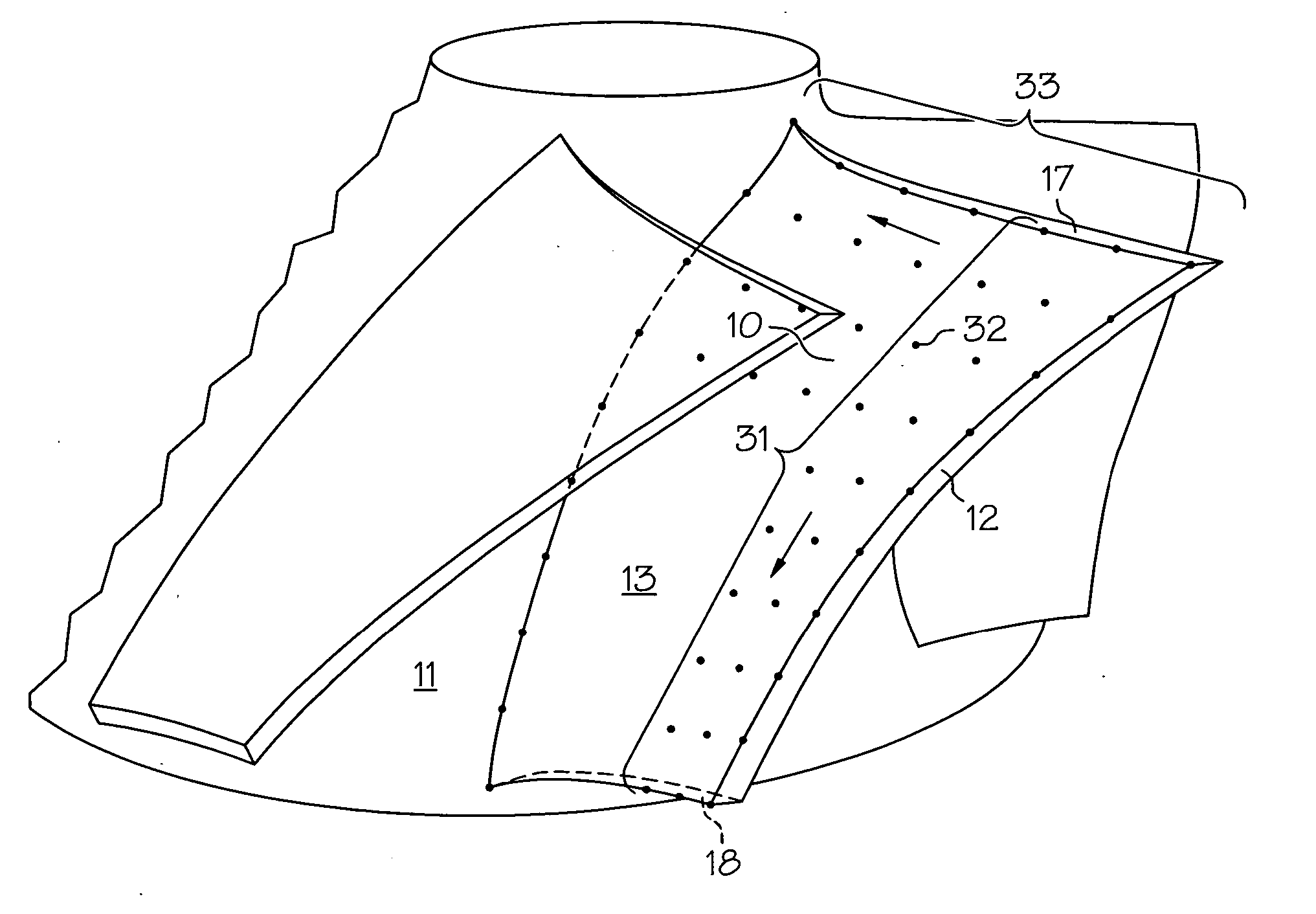
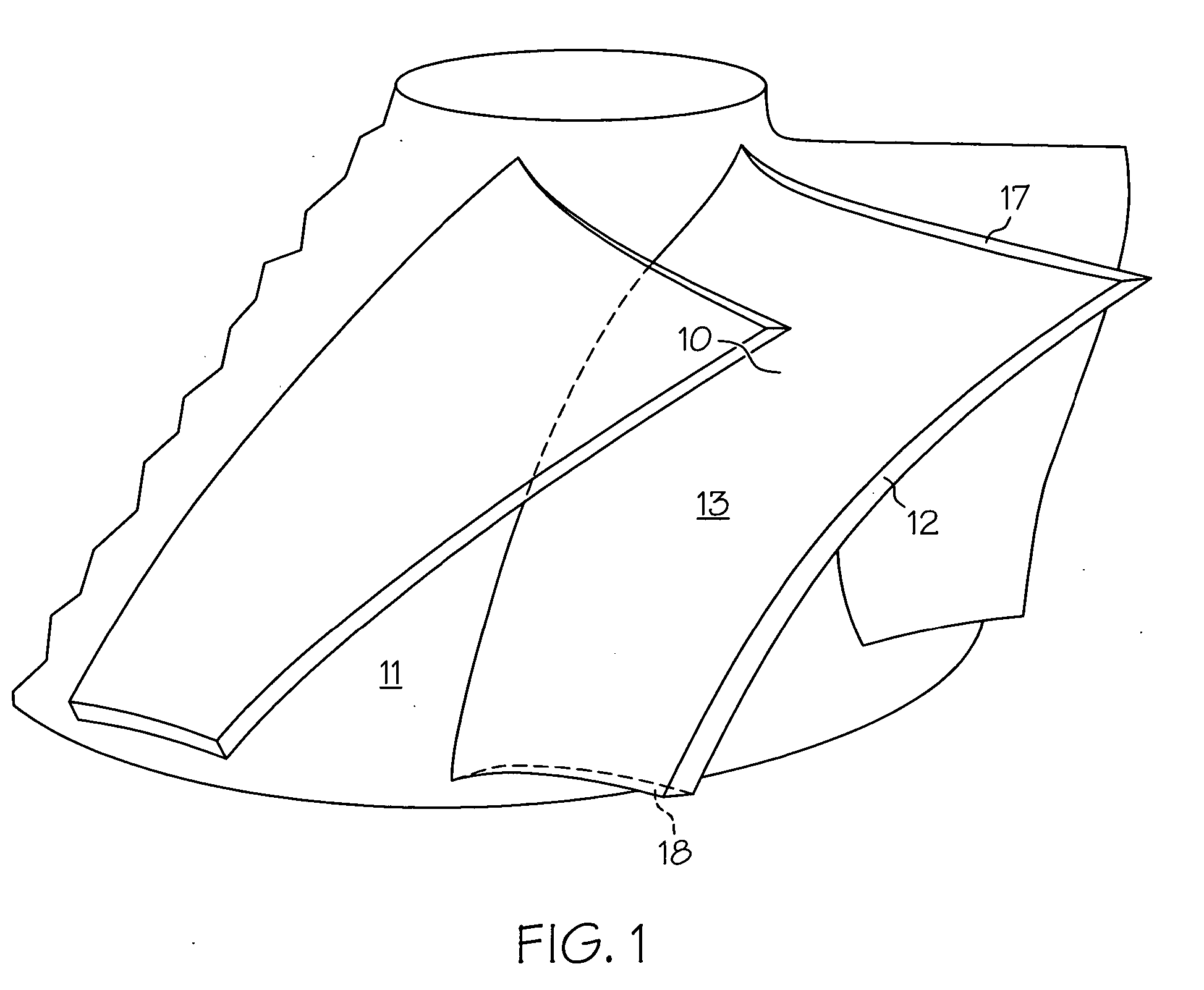
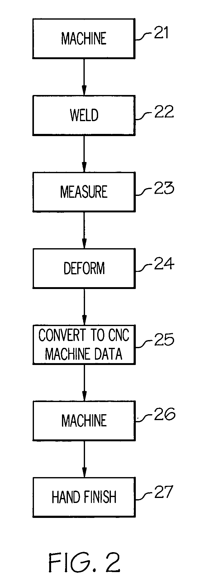
[0020] It has now been discovered that an improved machining and weld repair process can be achieved through the use of adaptive machining technology. In overview, the process first machines away damaged portions of an airfoil. Filler material is then added to the machined area through a process such as laser welding. At this point, the actual profile of the welded airfoil is measu...


PUM

PropertyMeasurementUnit
dimensionsaaaaaaaaaa
shapeaaaaaaaaaa
shape deviationaaaaaaaaaa

Abstract

The present invention provides an apparatus and method for an adaptive machining and weld repair process useful for repairing airfoils, particularly damage to an airfoil leading edge and tip. The process first machines away damaged portions of an airfoil. Filler material is then added to the machined area through a process such as laser welding. At this point, the actual profile of the welded airfoil is measured using a Coordinate Measuring Machine. This data is then used to generate a “deformation” profile, an airfoil profile that approximates the ideal shape of the airfoil. The airfoil is then machined using the date of the deformation profile to produce that shape. The adaptive technology minimizes the amount of stock on material that needs to be removed by hand. The technique thereby significantly reduces costly manual processing.

Description

FIELD OF THE INVENTION [0001] The present invention relates to welding. More particularly the invention relates to the apparatus and techniques used for adaptive machining and weld repair. The invention further relates to adaptive machining and weld repair as related to impellers and blisks used in gas turbine engines. BACKGROUND OF THE INVENTION [0002] Turbine engines are used as the primary power source for many types of aircrafts. The engines are also auxiliary power sources that drive air compressors, hydraulic pumps, and industrial gas turbine (IGT) power generation. Further, the power from turbine engines is used for stationary power supplies such as backup electrical generators for hospitals and the like. [0003] Most turbine engines generally follow the same basic power generation procedure. Compressed air generated by axial and / or radial compressors is mixed with fuel and burned, and the expanding hot combustion gases are directed against stationary turbine vanes in the engi...

Claims


Application Information

Patent Timeline
Patent Type & Authority Applications(United States)
IPC IPC(8): B23P6/00
CPCB23P6/007F01D5/005F05D2230/234F05D2230/80B23K26/345Y10T29/49229Y10T29/49336Y10T29/49318Y10T29/49238Y10T29/49236Y10T29/49233B23K35/0244B23K26/342Y02T50/60
Inventor GRAHAM, JAMES H.REINWAND, JEFFREYCORIELL, ROGER G.LYTLE, KEVIN
Owner HONEYWELL INT INC
Why Eureka
Try Eureka