Thermal deformation error compensation method for coordinate measuring machine

a technology of error compensation and coordinate measuring machine, which is applied in the direction of speed/acceleration/shock measurement, instruments, surveying and navigation, etc., can solve the problems of complex and difficult creation of a mathematical model for thermal deformation, and the general manufacture operating environment control (such as temperature and humidity, etc.) is not as good as the control in the precision-measurement laboratory

Inactive Publication Date: 2010-11-25
CARMAR TECH
View PDF3 Cites 66 Cited by
  • Summary
  • Abstract
  • Description
  • Claims
  • Application Information

AI Technical Summary

Benefits of technology

[0011]Create actual thermal deformation and geometric error data: including the measured data required for creating the thermal deformation and geometric error model. The measuring method and procedure include the steps of controlling an environment to a specific temperature in a temperature-controlled laboratory, using a controller of the coordinate measuring machine to drive a linear motion axis to situate at a specific position, using a high-precision measuring apparatus (such as a laser interferometer) to perform an actual positioning measurement of a geometric error when a moving machine table is situated at a different position, and then going through a format processing to convert into the same coordinate system and reading format of the thermal deformation and geometric error model. The temperature of the temperature-controlled laboratory is set to another specific temperature, and the aforementioned measurement is repeated to obtain data of errors of the thermal deformation and geometric error terms of the coordinate measuring machine at different specific temperatures and the data are inputted into a control unit of the coordinate measuring machine.

Problems solved by technology

Firstly, a non-linear relation exists between thermal expansion coefficient and temperature of various different components and materials of the coordinate measuring machine.
Secondly, the thermal deformation model is complicated since the stresses produced by the change of temperature will affect one another after the components of the coordinate measuring machine are assembled.
Thirdly, a non-uniform temperature field is produced by a change of space for disposing the coordinate measuring machine or an internal heat source, and the non-uniform temperature field will make the creation of a mathematical model for the thermal deformation more complicated and difficult.
In addition, the coordinate measuring machines tend to be used extensively in manufacture, but a general manufacture operating environment control (such as temperature and humidity, etc) is not as good as the control in a precision-measurement laboratory.
However, the improvements made to the mechanical design, the environment and the equipment are insufficient to eliminate the geometric errors and thermal deformations completely.

Method used


Image

  • Thermal deformation error compensation method for coordinate measuring machine
  • Thermal deformation error compensation method for coordinate measuring machine
  • Thermal deformation error compensation method for coordinate measuring machine

Examples


Embodiment Construction

[0020]With reference to FIGS. 1 to 7, the present invention will now be described in more detail hereinafter with reference to the accompanying drawings that show various embodiments of the invention, and these embodiments are provided for illustrating the present invention, but not intended to limit the scope of the present invention.

[0021]This embodiment provides a thermal deformation error compensation method for a coordinate measuring machine. Firstly, a geometric error term of the coordinate measuring machine (CMM) is described as follows:

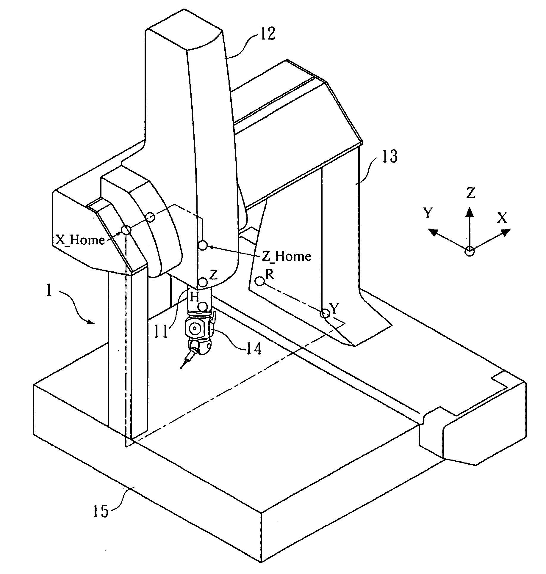
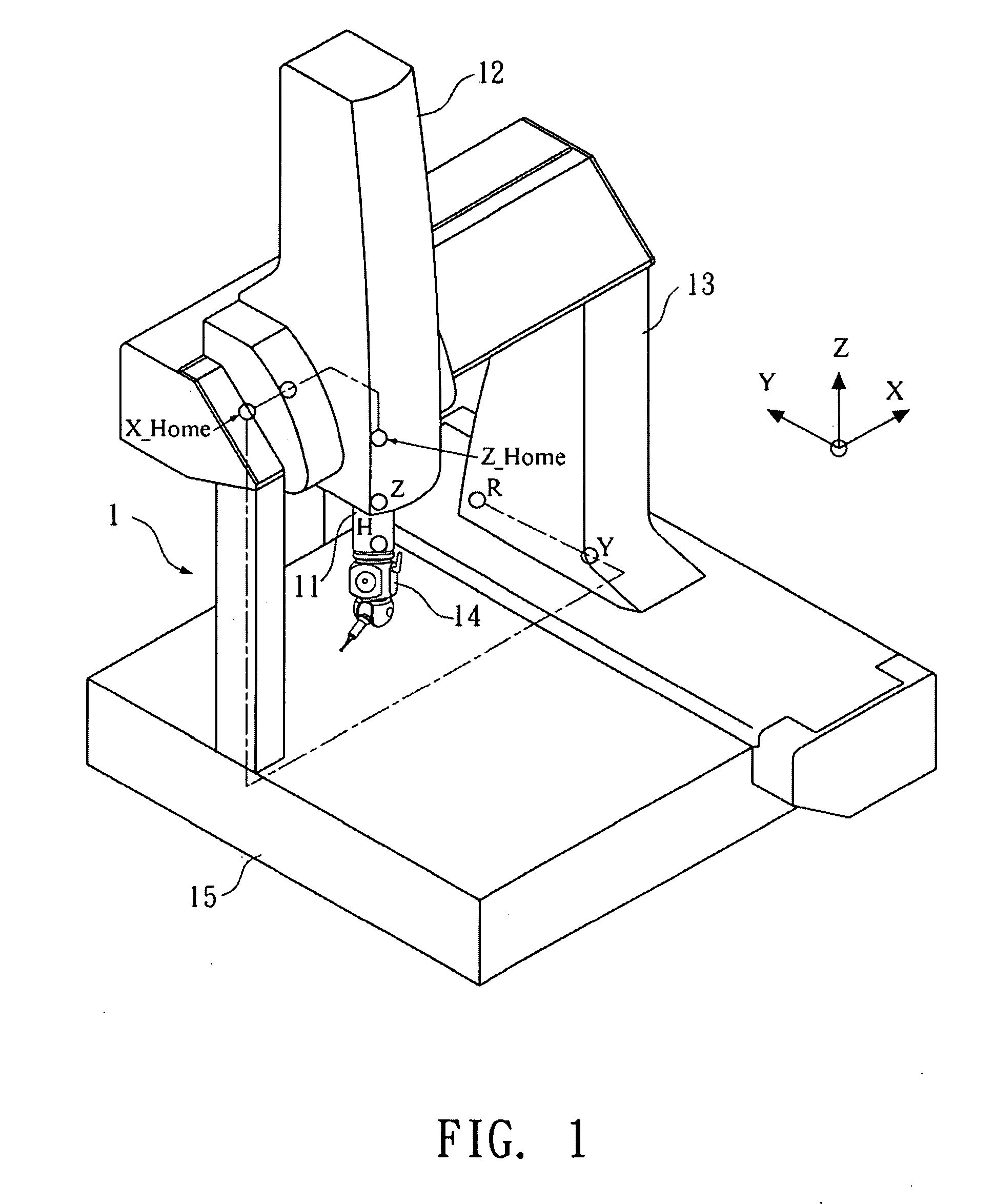
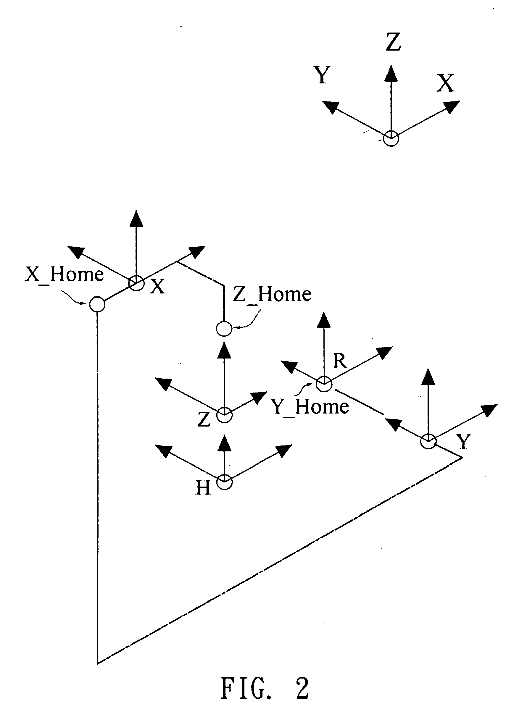
[0022]With reference to FIGS. 1 and 2 for a coordinate measuring machine 1 and its coordinate system in accordance with a preferred embodiment of the present invention, mechanical chains of the coordinate measuring machine 1 are interconnected and have three linear axes (X,Y,Z). The mechanical chain includes a Z-axis sliding table 11 moving along the Z-axis, and built on a X-axis sliding table 12, and the X-axis sliding table 12 is built on a ...


PUM


Abstract

A thermal deformation error compensation method for a coordinate measuring machine creates thermal deformation and geometric error data at different ambient temperatures including temperatures and machine kinematic parameters to obtain a thermal deformation and geometric error model, and inputs the model into central control unit of the coordinate measuring machine, and converts a 3D error compensation to obtain a thermal deformation and geometric error compensation model, and uses the thermal deformation and geometric error compensation model for performing compensations, so as to complete a thermal deformation and geometric error compensation of the coordinate measuring machine.

Description

FIELD OF THE INVENTION[0001]The present invention relates to a thermal deformation error compensation method for a coordinate measuring machine, in particular to a method of compensating an error produced by a thermal deformation of a coordinate measuring machine in environments of different temperatures.BACKGROUND OF THE INVENTION[0002]As the definition of a geometric error model of a coordinate measuring machine does not take a change of temperature into consideration, a volume (3D) error is positioned at a tool end at any position of the machine motion space. The coordinate measuring machine uses a plurality of independent geometric error terms to represent a volume error of a tool end of the machine caused by a geometric error, and derive a geometric error model according to a mechanical chain of the machine. The aforementioned error terms are substituted into the geometric error model to estimate the volume error at the tool end when the machine is moved to any position in a sp...

Claims


Application Information

Patent Timeline
Patent Type & Authority Applications(United States)
IPC IPC(8): G06F19/00
CPCG01B21/045G01B5/0014
Inventor HSU, YUNG-YUAN
Owner CARMAR TECH
Why Eureka
Try Eureka