Inspection system using coordinate measurement machine and associated method

a coordinate measurement machine and inspection system technology, applied in the direction of mechanical measuring arrangements, instruments, image enhancement, etc., can solve the problems of inability to produce a more accurate c-scan or b-scan for small to midsize complex parts, less desired a-scans, and parts that are in danger of being used, so as to increase the probability of detecting a defect in a workpiece

Active Publication Date: 2009-03-24
THE BOEING CO
View PDF12 Cites 67 Cited by
  • Summary
  • Abstract
  • Description
  • Claims
  • Application Information

AI Technical Summary

Benefits of technology

[0010]The invention addresses the above needs and achieves other advantages by providing an inspection system capable of generating various scans for inspecting a workpiece. The inspection system incorporates a portable coordinate measurement machine and data acquisition system to produce, in some embodiments, C-scans, which increases the probability of detecting a defect in a workpiece.
[0014]The present invention therefore provides an inspection system capable of generating A-scan, B-scan, and C-scan images that increase the probability of detecting a defect in a workpiece. Increasing the probability of detecting a defect increases the reliability of the inspection system. The data acquisition system generates images that permit the inspection of a critical or complex workpiece to be monitored, such as by a vendor or supervisor. In addition, the CMM, including one movable arm, provides several degrees of freedom, which allows the sensor to be moved along workpieces of various dimensions and materials. The inspection system is advantageously portable so that it may be used in a variety of locations and even remotely from a central inspection location.

Problems solved by technology

Manual inspection systems such as the USN60 (GE Inspection Technologies) and the Epoch III (Panametrics, Inc.) are typically used for portable inspection of in-service and as-manufactured parts, but are only capable of producing an A-scan output inspection.
A-scans are less desired as customers become concerned about the probability of detecting a defect when employing the manual inspection of fracture and durability (F / D) parts, which puts the part in jeopardy of being not approved for use.
Thus, current manual inspection systems are incapable of producing a more accurate C-scan or B-scan for small to midsize complex shaped parts.

Method used


Image

  • Inspection system using coordinate measurement machine and associated method
  • Inspection system using coordinate measurement machine and associated method
  • Inspection system using coordinate measurement machine and associated method

Examples


Embodiment Construction

[0018]The present invention now will be described more fully hereinafter with reference to the accompanying drawings, in which some, but not all embodiments of the invention are shown. Indeed, this invention may be embodied in many different forms and should not be construed as limited to the embodiments set forth herein; rather, these embodiments are provided so that this disclosure will satisfy applicable legal requirements. Like numbers refer to like elements throughout.

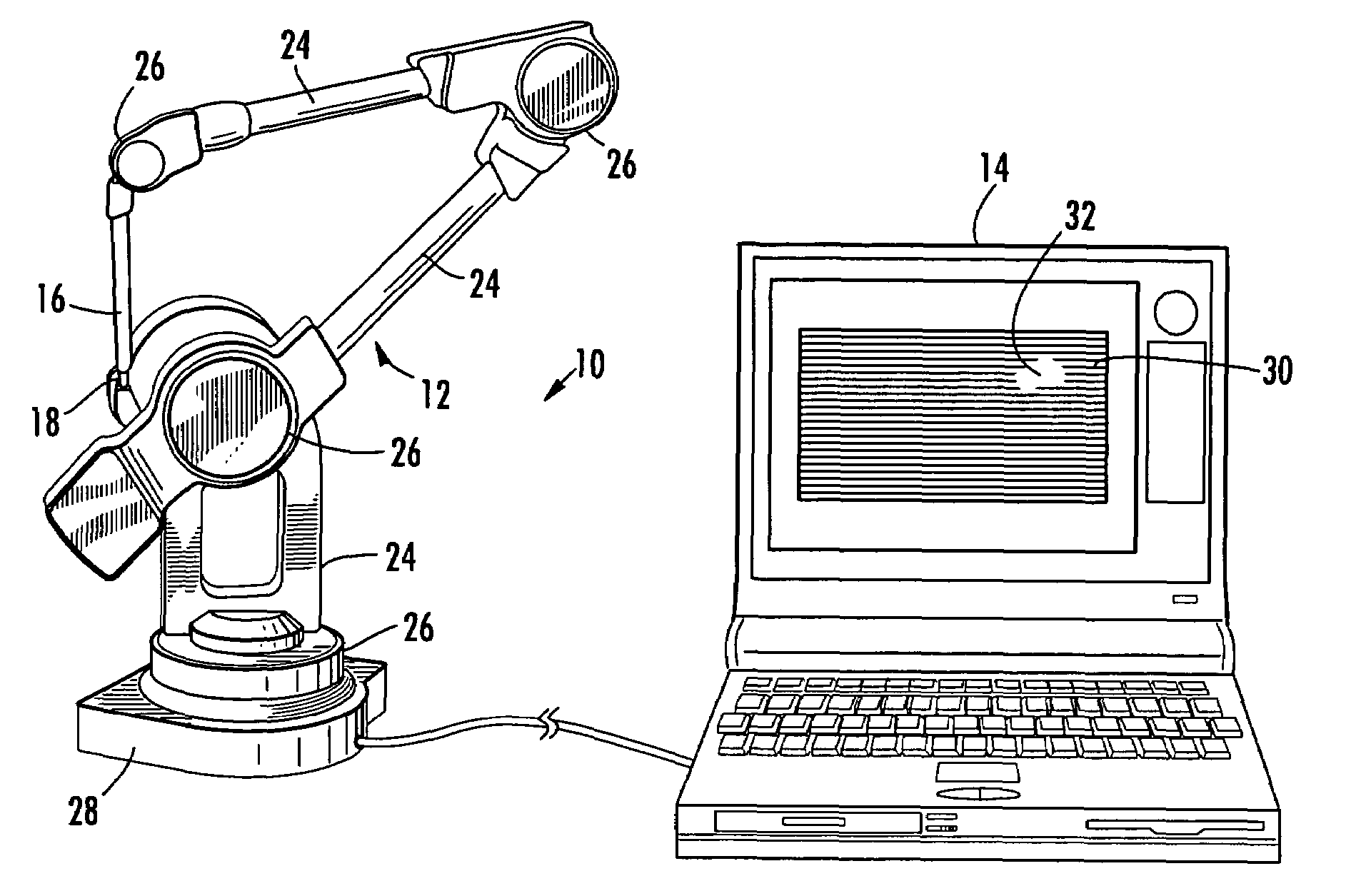
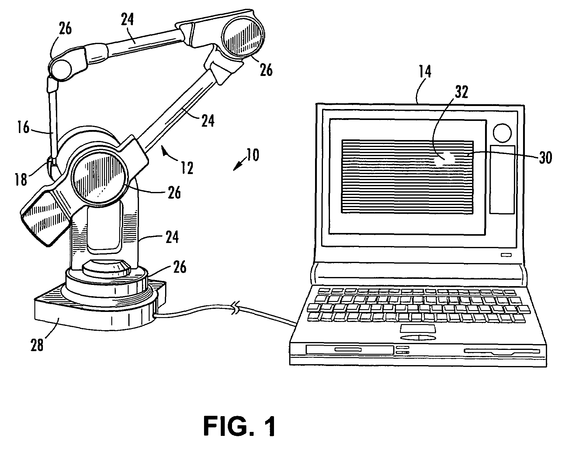
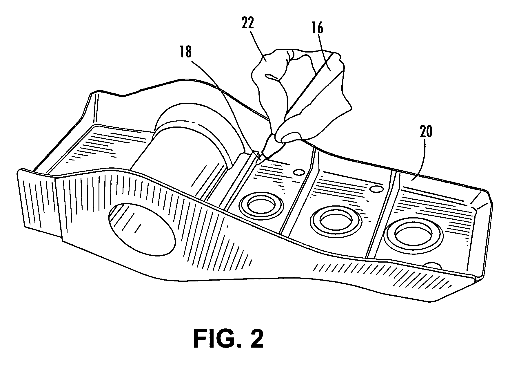
[0019]Referring now to the drawings and, in particular to FIGS. 1-2, there is shown an inspection system 10. The inspection system 10 includes a coordinate measurement machine (CMM) 12 in communication with a data acquisition system 14. As a sensor 18, carried by a stylus 16, is moved along a workpiece 20, data is sent to the data acquisition system 14 for processing. Typically, a user 22 manually holds the stylus 16 while moving the sensor 18 proximate to the workpiece 20, while the data acquisition system 14 gen...


PUM


Abstract

A system and method for identifying defects in a workpiece are provided. The system includes a sensor for non-destructive testing. The system also includes a movable arm carrying the sensor and being pivotally attached to a base. The movable arm includes at least one pivotable joint between the base and the sensor, and is capable of being moved such that the sensor acquires data indicative of a workpiece as the sensor travels proximate to the workpiece. A data acquisition system is capable of communicating with the sensor to create an image of at least a portion of the workpiece based on the data acquired by the sensor.

Description

BACKGROUND OF THE INVENTION[0001]1) Field of the Invention[0002]The present invention relates to non-destructive inspection and, more particularly, to non-destructive inspection of a workpiece for defects using an inspection system in conjunction with a coordinate measurement machine and data acquisition system, as well as an associated method.[0003]2) Description of Related Art[0004]Non-destructive testing of structures involves thoroughly examining a structure without harming, or requiring significant disassembly of, the structure. Non-destructive testing is advantageous for many applications in which a thorough inspection of the exterior and / or interior of a structure is required. For example, non-destructive testing is commonly utilized in the aircraft industry to inspect aircraft structures for any type of internal or external damage to the structure. Metallic aircraft structures are typically inspected for corrosion and / or cracking, particularly near fasteners in the structure...

Claims


Application Information

Patent Timeline
Patent Type & Authority Patents(United States)
IPC IPC(8): G06K9/00G01B5/008G06T7/00
CPCG01B5/008G06T7/0004G06T7/0051G06T2207/30164G06T7/50
Inventor VACCARO, CHRISTOPHER M.WOOD, NANCY L.
Owner THE BOEING CO
Why Eureka
Try Eureka