
Target detection method and system

a target detection and target technology, applied in the field of image processing methods and systems, can solve the problems of object or target detection, requires relatively high processor speed for a given target detection performance, and requires relatively intensive processing, so as to improve the efficiency and performance of detection

Inactive Publication Date: 2008-09-30
LOCKHEED MARTIN CORP
View PDF8 Cites 52 Cited by
  • Summary
  • Abstract
  • Description
  • Claims
  • Application Information

AI Technical Summary

Benefits of technology

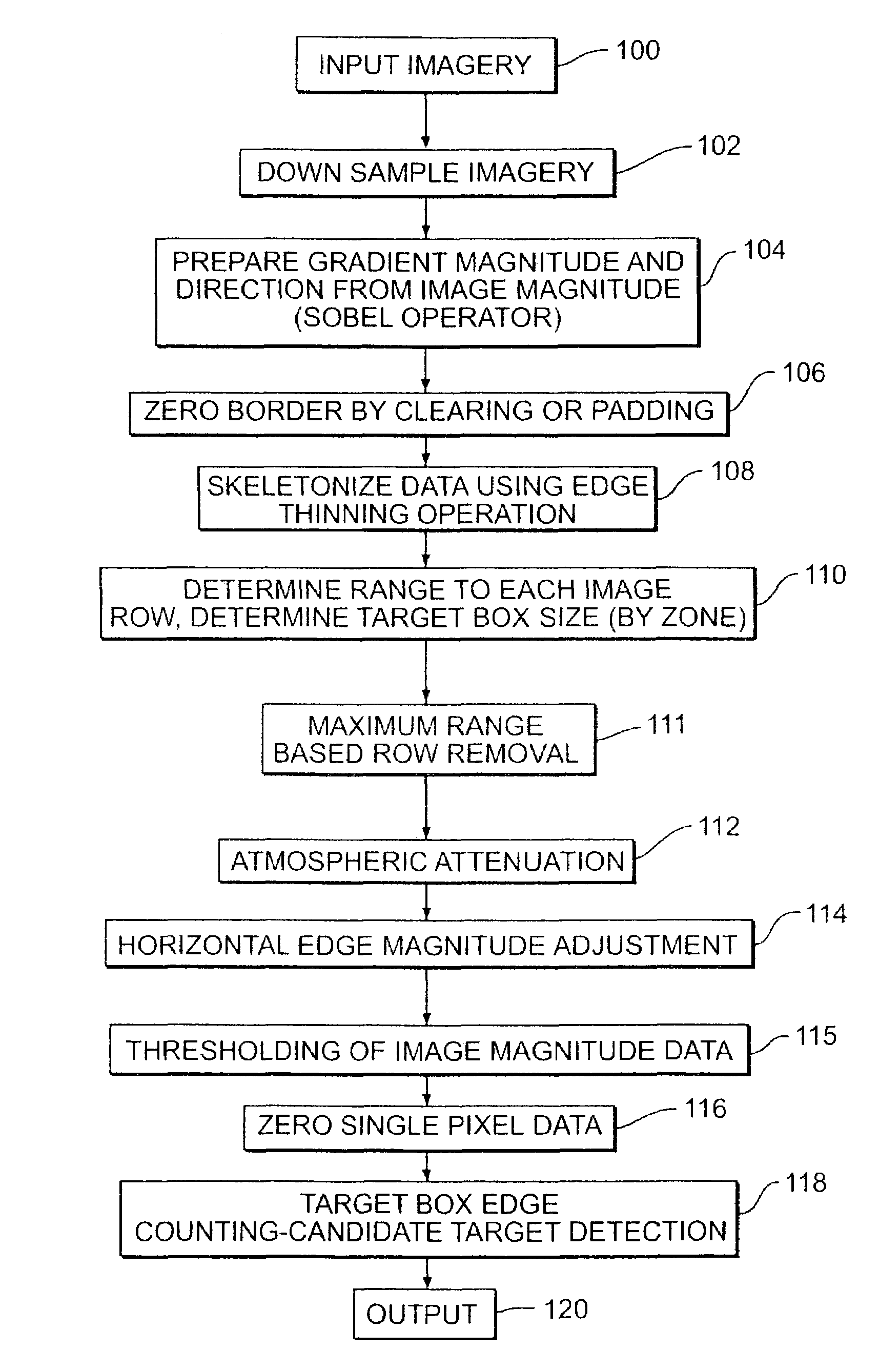
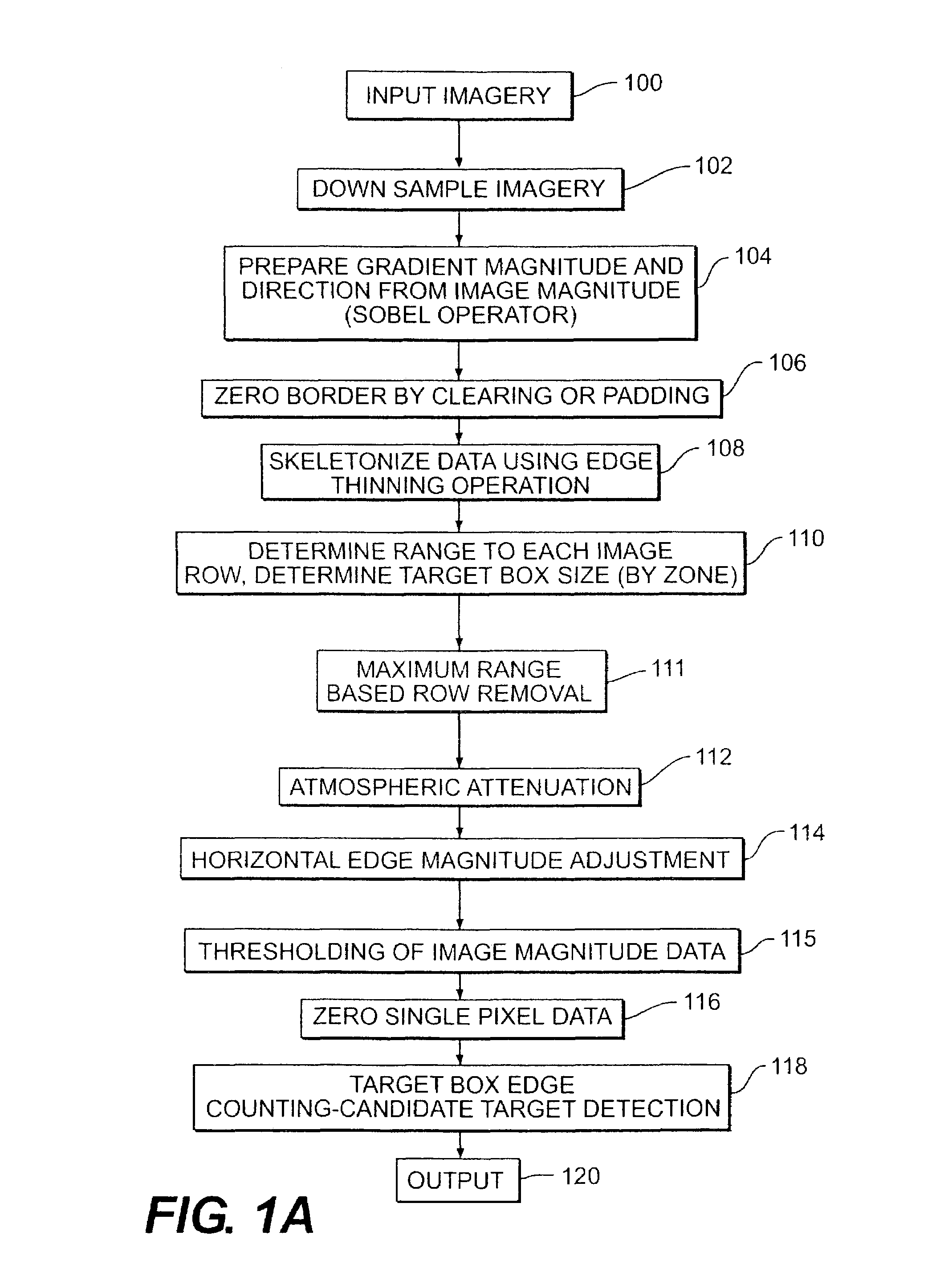
[0006]While a number of target detection techniques are known, the system and method of the present application uses a combination of techniques to improve target detection and discrimination without undesired increases in the rate of false alarms. The algorithm processing techniques used in accordance with the teachings of the present application seek to improve candidate target identification performance while retaining reasonable processing load, enabling (although not requiring) the use of available a single processor.
[0007]In one exemplary embodiment, by attaching the algorithm to the front end of an infrared imaging tracker algorithm, the ability to correctly determine and separate targets from non-targets is increased. Thus, by utilizing the techniques of the present application, the false alarm rate decreases while the probability of detecting targets increases.
[0008]The system and method of the present application desirably use a number of techniques to simplify processing of acquired imagery and improve the successful identification of candidate targets while reducing both processing load and false target identification. A combination of these techniques produces unexpectedly improved performance and is in itself an important advance. However the individual techniques making up this combination are similarly advances in the art.
[0009]For example, the use of an atmospheric attenuation compensation algorithm compensates for range related image deterioration, particularly in infrared sensing systems.
[0010]The attenuation of the effect of horizontal edges in the detected imagery due to, for example, tree lines and roads, is beneficial in reducing the effect such horizontal lines have on the detection of adjacent features.
[0012]In one embodiment, detection of objects or targets in the image data is performed by identifying areas where a large diversity of edge directions in a region of interest. This technique is enhanced by defining the region of interest as a target box sized in relation to the expected target size in accordance with another aspect of the invention.

Problems solved by technology

One of the more difficult aspects of object or target detection is to improve the detection of objects or targets while minimizing False Alarms.
The approach disclosed in Reis et al. primarily uses hierarchical edge based analysis and requires relatively intensive processing requiring relatively great processor speed for a given target detection performance.

Method used


Image

  • Target detection method and system
  • Target detection method and system
  • Target detection method and system

Examples


case 1

[0090]If sensor Height[0091]Target Range for all 256 rows=LOS Target Range

[0092]

υd = (360 / π) × tan−1(hT) / RThd = υd × RW / Hυs = nα×υdhs nα× hdwhere υs is the vertical size of target in pixels and hs is the horizontal size of target in pixels

Case 2[0093]If angle at row(i)[0094]Target Range at row(i)=2*maximum range

These cases prevent the values from being negative unduly complicating processing.

[0095]Zone Generation

[0096]Desirably, the target box size need not be continuously varied as range varies within the image. Consequently, it is desirable to vary the target box size while keeping each target box of a constant size within a zone of the image. Consequently, the image gradient magnitude and direction data is preferably divided into plural zones of constant target box size (constant target height).

[0097]The specific zones in the imagery are generated by the following procedure. First, find the minimum and maximum values in the min verPixSize array. This array is assembled based on t...


PUM


Abstract

A method and system detects candidate targets or objects from a viewed scene by simplifying the data, converting the data to gradient magnitude and direction data which is thresholded to simplify the data. Horizontal edges within the data are softened to reduce their masking of adjacent non-horizontal features. One or more target boxes are stepped across the image data and the number of directions of gradient direction data within the box is used to determine the presence of a target. Atmospheric attenuation is compensated. The thresholding used in one embodiment compares the gradient magnitude data to a localized threshold calculated from the local variance of the image gradient magnitude data. Imagery subsets are containing the candidate targets may then be used to detect and identify features and apply a classifier function to screen candidate detections and determine a likely target.

Description

[0001]This application claims priority on provisional Application No. 60 / 368,150 filed on Mar. 29, 2002, the entire contents of which are hereby incorporated by reference.FIELD OF THE INVENTION[0002]The present invention relates to image processing methods and systems including a processor utilizing an algorithm for processing acquired imagery data and more particularly to such a method, system and associated algorithm for identifying candidate objects or targets from background imagery data.BACKGROUND OF THE INVENTION[0003]There are many situations where imagery data is collected for the purpose of detecting candidate objects or targets from collected background data. One of the more difficult aspects of object or target detection is to improve the detection of objects or targets while minimizing False Alarms. Processing and computing requirements for a given target detection performance are also highly variable. Obviously, it is desirable to improve target detection capability whi...

Claims


Application Information

Patent Timeline
IPC IPC(8): G06K9/00G06K9/32
CPCG06K9/3241G06V10/255
Inventor SEFCIK, JASONLEE, HARRY C.OLSON, TERESA L.
Owner LOCKHEED MARTIN CORP
Learn More