Wireless breach detection

a technology of breach detection and wireless connection, applied in the field of medical devices and methods, to achieve the effect of improving sensitivity and reliability of detection

Active Publication Date: 2006-05-25
FULFILLIUM
View PDF64 Cites 44 Cited by
  • Summary
  • Abstract
  • Description
  • Claims
  • Application Information

AI Technical Summary

Benefits of technology

[0015] Alternatively, the circuit components may include spaced-apart conductors which are electrically coupled to the signaling circuit to “close” the signaling circuit to permit current flow when exposed to a body fluid and/or inflation medium by a wall breach. In the exemplary embodiments described below, the conductors may comprise meshes, films, or other relatively large surface areas covering most or all of the wall so that breach at any point in the wall will provide the intended electrically conductive bridging between the conductors. The coupling of the conductors may also cause, alter, or enable a signal emission to alert the patient of the breach or potential breach. The spaced-apart conductors can have any one of a variety of shapes or configurations, continuous configurations, such as plates and films, or discontinuous configurations, such as lattices, meshes, and the like, can be placed in various locations, preferably near interior portions of the device where body fluids will pool to enhance sensitivity an

Problems solved by technology

These and other devices may contain potentially bioincompatible mater

Method used


Image

  • Wireless breach detection
  • Wireless breach detection
  • Wireless breach detection

Examples


Embodiment Construction

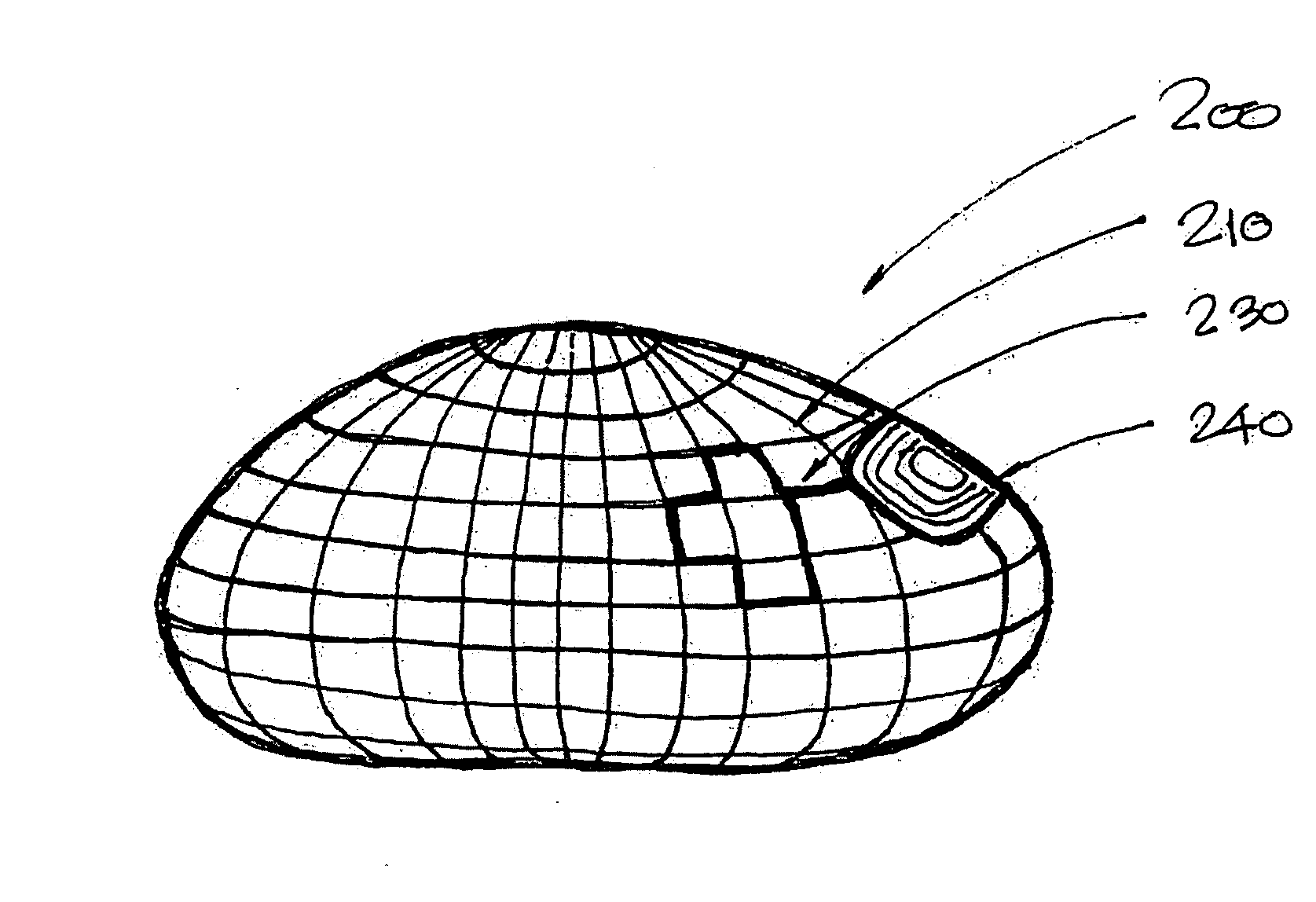
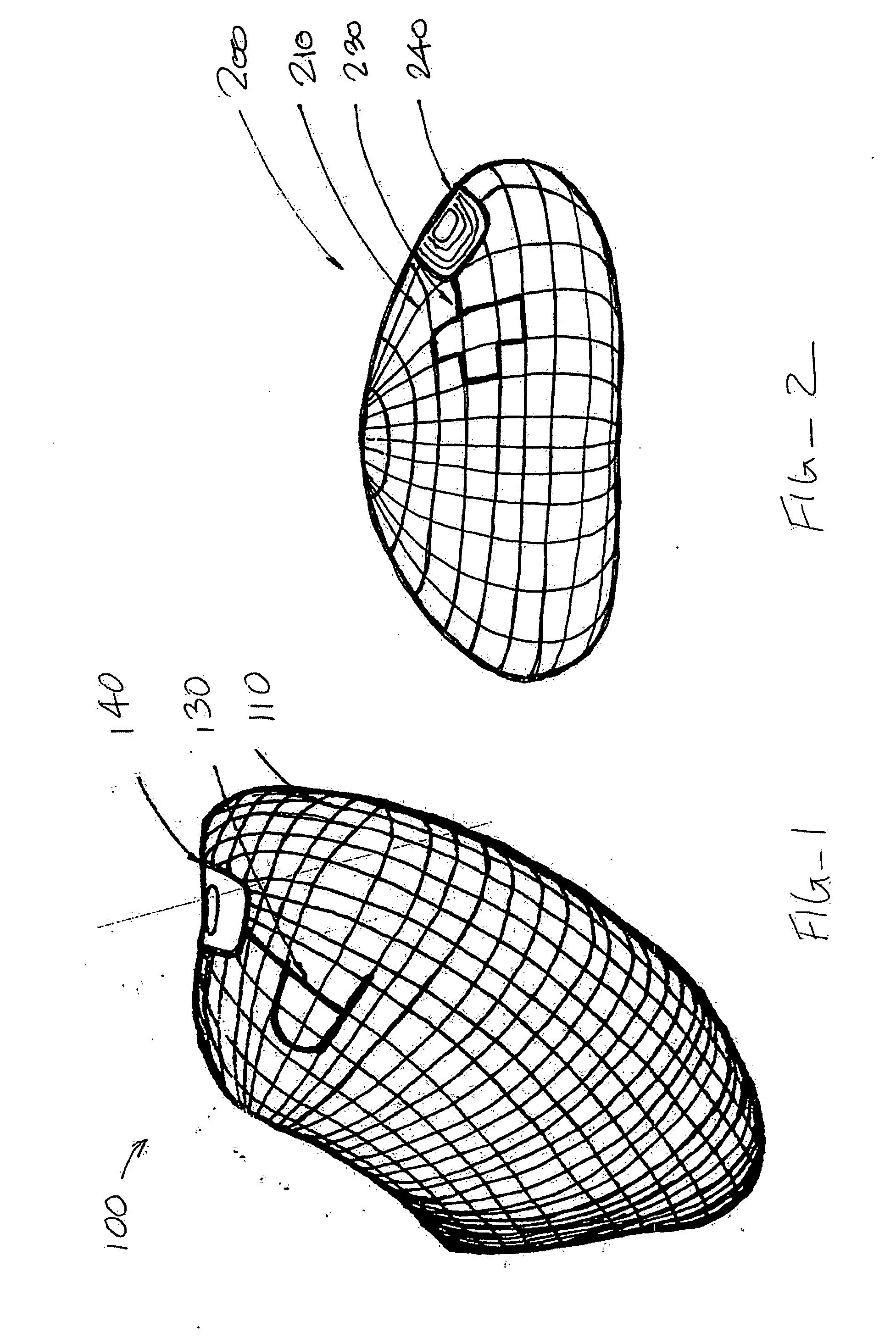
[0033] Referring now to FIG. 1, the gastric balloon 100 includes two electric probes. Probe 130 is on the external surface in contact with the surrounding tissues, body fluids, and contents of the stomach. Probes 130 and 110 can have any of a variety of shapes or configurations, including circular plates, lattices, films, and the like, cover all or a portion of the balloon or other device. Probe 110, shown here in a lattice configuration, provides the second probe incorporated in the wall of the balloon. The probe material could be any metal, polymer, fiber, or combination thereof, with or without any coating that can generate an electrical charge or enable flow of electric current when in contact with the stomach contents. The probes are connected electronically to the wireless transmitter 140, but are separated from each other by at least one layer of non-conductive material in the balloon wall. The transmitter can be a simple wireless signal generator triggered by an electric cur...


PUM


Abstract

Methods and systems for detecting wall breach in inflatable prostheses rely on intrusion of a body fluid or inflation medium to electrically alter a signaling circuit. In one embodiment, an open portion of a circuit is closed to enable or modify a transmitted signal. In another embodiment, electrical current is generated to power an electrical transmission.

Description

CROSS-REFERENCES TO RELATED APPLICATIONS [0001] The present application is a continuation-in-part of application Ser. No. 11 / 122,315 (Attorney Docket No. 022209-000230US), filed on May 3, 2005, and claims the benefit under 35 USC §119(e) of prior provisional application No. 60 / 629,800 (Attorney Docket No. 02209-000210US), filed on Nov. 19, 2004, the full disclosures of which are incorporated herein by reference.BACKGROUND OF THE INVENTION [0002] 1. Field of the Invention [0003] The present invention relates generally to medical apparatus and methods. More particularly, the present invention relates to implantable devices and methods and systems for detecting their failure or impending failure. [0004] All implants of devices, esp. those indicated for long term use, in the human body are highly regulated and must meet certain safety requirements. One such requirement is biocompatibility of the materials used in the construction of the device in the event they come into direct contact ...

Claims


Application Information

Patent Timeline
IPC IPC(8): A61F2/12A61F2/04
CPCA61F2/12A61F2/26A61F5/003A61F2250/0002A61N1/08A61N1/3706A61F5/0036A61F5/0046A61F2210/0061A61F2250/0003A61F2250/008A61B5/076A61B5/686A61B5/7282A61B5/746G08B21/18
Inventor CHEN, RICHARD D.Y.
Owner FULFILLIUM
Why Eureka
Try Eureka