Switches

A switching device and sliding block technology, which is applied to electric switches, snap-action devices, electrical components, etc., can solve the problem that the control rod part 32 cannot be reset, and achieve the effect of improving assembly efficiency

Active Publication Date: 2010-05-12
ALPS ALPINE CO LTD
View PDF6 Cites 0 Cited by
  • Summary
  • Abstract
  • Description
  • Claims
  • Application Information

AI Technical Summary

Problems solved by technology

[0012] Also, similarly, there is a disadvantage that the control rod member 32 cannot be reset to such a position due to the relaxation of the stress of the movable contact 35. Figure 12 The initial state shown

Method used


Image

  • Switches
  • Switches
  • Switches

Examples


Embodiment Construction

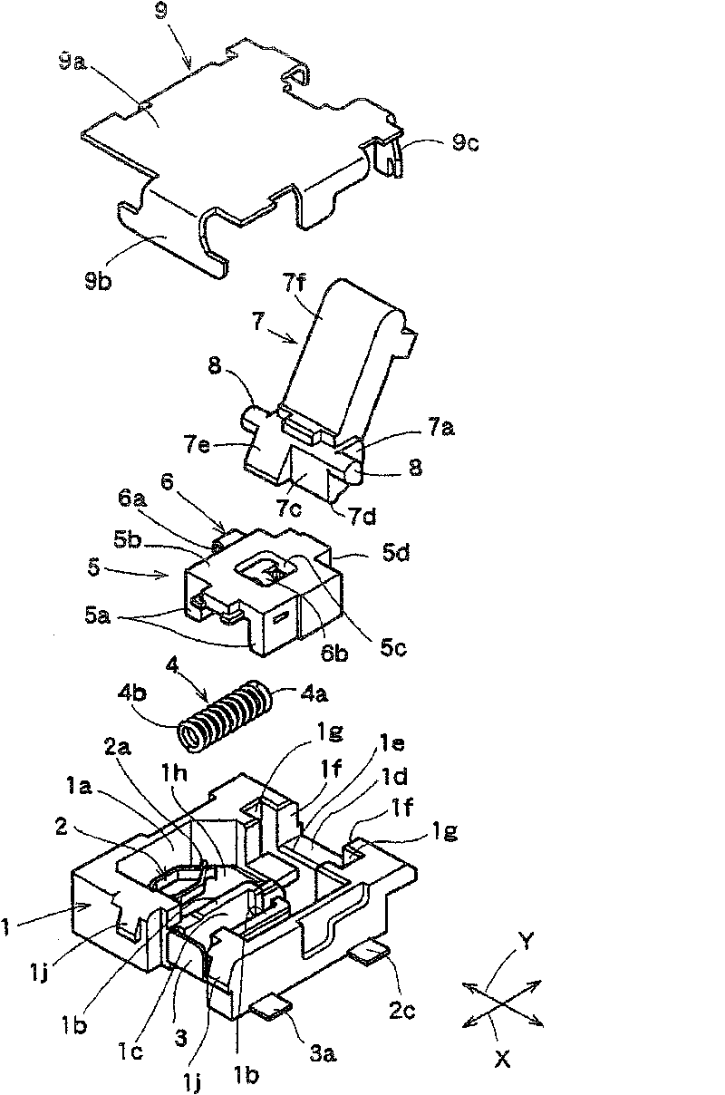
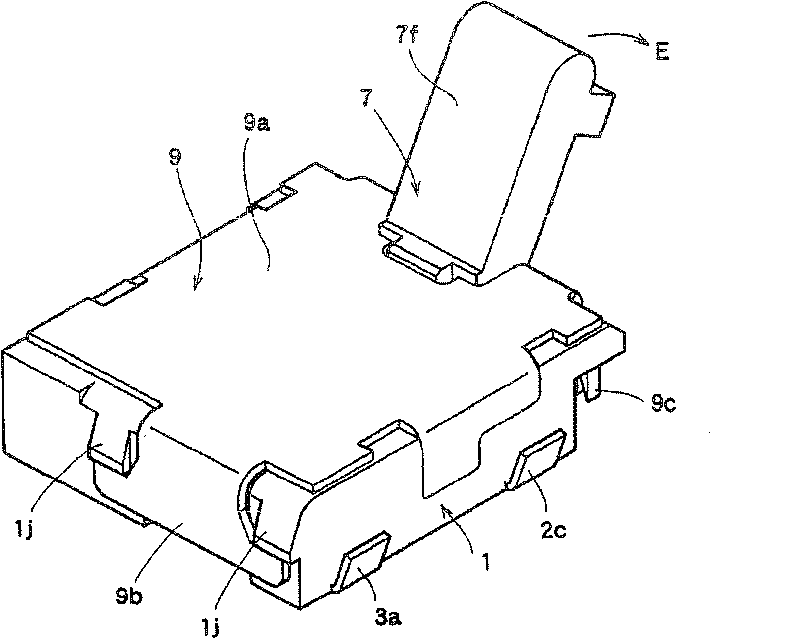
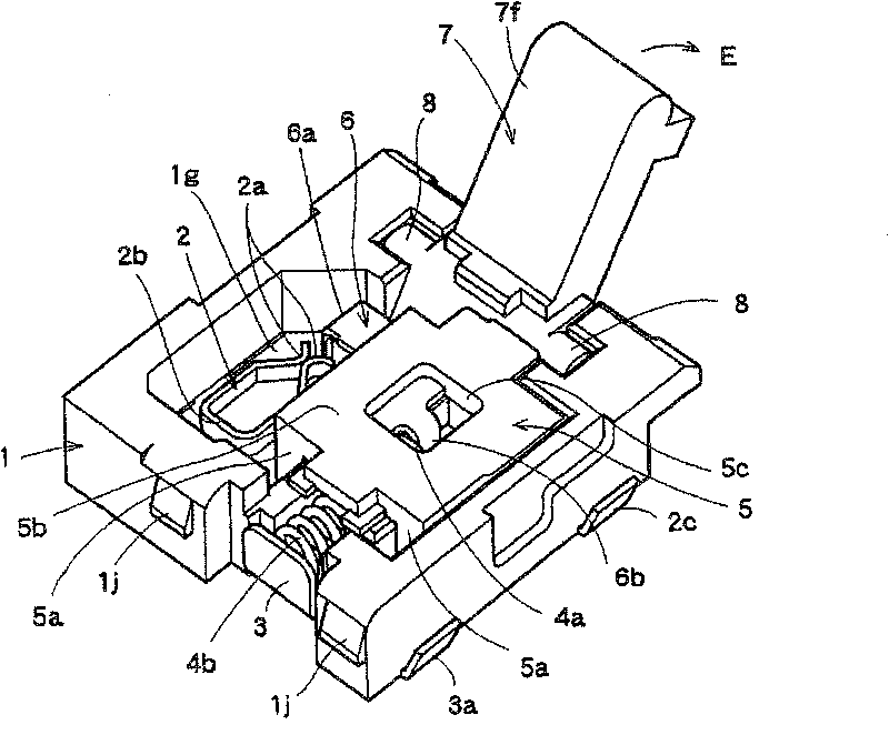
[0087] Hereinafter, embodiments of the switch device of the present invention will be described based on the drawings. figure 1 is an exploded perspective view of the switchgear of the present invention, figure 2 is a perspective view of the switch device of the present invention, image 3 From figure 2 A perspective view of the state with the cover removed in Figure 4 It is a sectional view of main parts of the switchgear of the present invention, Figure 5 is a perspective view of the joystick assembly, Image 6 Yes Figure 5 side view, Figure 7 ~ Figure 9 is a diagram illustrating the operation of the lever parts, Figure 10 It is a sectional view of main parts for explaining another embodiment of the present invention.

[0088] First, based on Figure 1 ~ Figure 4 A switch device according to a first embodiment of the present invention will be described. in such as figure 1 The housing 1 made of a resin material or the like is disposed at the lowermost port...


PUM


Abstract

The related switch comprises: one end (4a) of spiral spring (4) contacted with a public point (3), another end (4b) contacted with an active point (6), a control bar (7) rotary supported the shell (1), and a slide block (5) fit to slide to another side and contact the points of (2) and (6). This invention can improve device strength and work reliability.

Description

technical field [0001] The present invention relates to a switch device, and relates to a switch device that can be used in various electronic devices such as detection of opening and closing of a cover of a CD player, for example. Background technique [0002] If the existing switch device is described with Patent Document 1, then the existing switch device 30, such as Figure 11 As shown, an opening portion 31 a of the housing 31 is formed, and a lever member 32 is rotatably held on a rotation holding portion 31 b of the housing 31 by a shaft portion 32 a thereof. [0003] The drive part 32b of the lever member 32 is accommodated in the case 31, and the operation part 32c protrudes obliquely upward to the left. In addition, the shaft portion 32a of the lever member 32 strives to extend the distance up to the driving portion 32b, and makes the Figure 12 The illustrated switch device 30 has a thin thickness and is formed to have a small diameter within a rotatable range. ...

Claims


Application Information

Patent Timeline
Patent Type & Authority Patents(China)
IPC IPC(8): H01H21/36
CPCH01H5/04H01H5/06H01H21/22H01H21/42
Inventor 板桥隆幸
Owner ALPS ALPINE CO LTD
Why Eureka
Try Eureka