Distribution chute

A material distribution chute and discharge chute technology, which is applied in the field of material distribution chute, can solve the problems of high power consumption of electro-hydraulic push rods, difficulty in flipping the plate, and high production cost, so as to save driving power consumption and increase wear resistance. , the effect of improving the service life

Active Publication Date: 2017-11-10
SICHUAN HONGJIAN HEAVY MACHINERY MFG
View PDF9 Cites 0 Cited by
  • Summary
  • Abstract
  • Description
  • Claims
  • Application Information

AI Technical Summary

Problems solved by technology

The existing distributing trough drives the rotating shaft to rotate through the connecting rod to turn the flap over, which has high requirements for the connection between the rotating shaft and the main conveying chute and the connection between the connecting rod and the rotating shaft, and the production cost is high; at the same time, because The flap is thick and heavy, it is difficult to drive the flap to flip through the rotation of the shaft, and the electro-hydraulic push rod consumes a lot of power

Method used


Image

  • Distribution chute
  • Distribution chute

Examples


Embodiment Construction

[0018] The present invention will be further described below in conjunction with accompanying drawing.

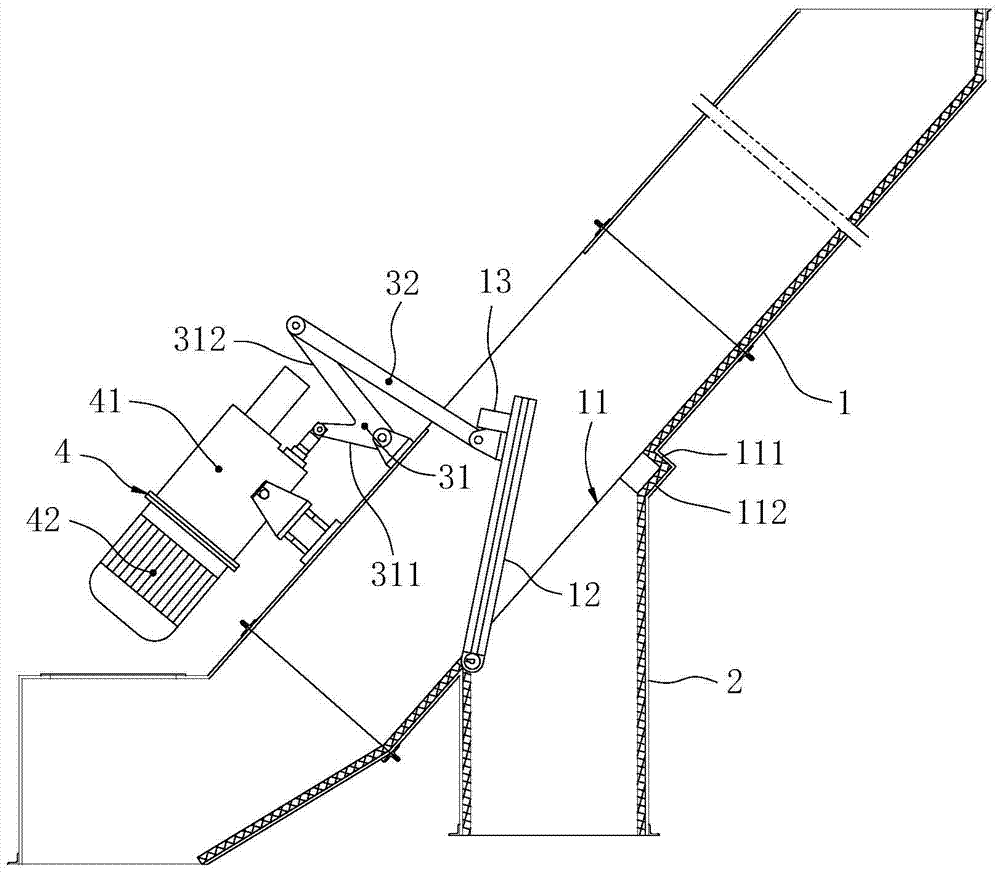
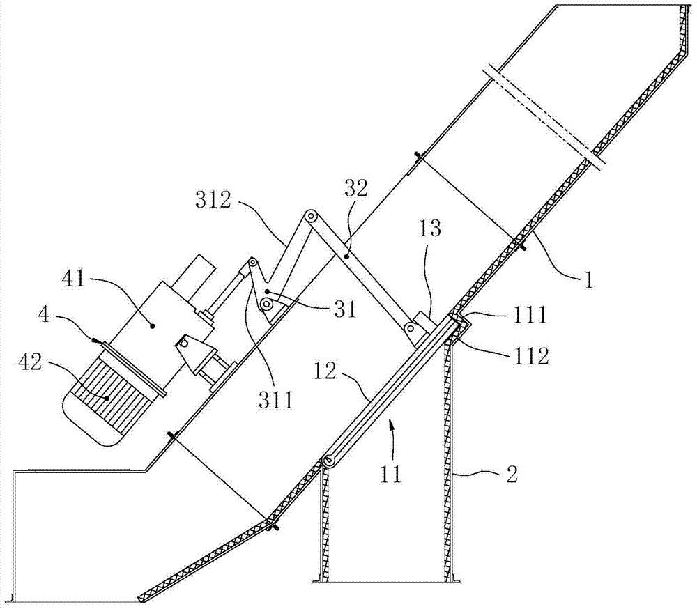
[0019] Such as figure 1 and figure 2 As shown, the distribution trough includes a main delivery chute 1 with a main discharge port at the lower end, an auxiliary discharge chute 2 arranged on the main delivery trough 1, a crank linkage mechanism and a driving mechanism 4; The opening 11 communicating with the auxiliary discharge chute 2 is provided with a flap 12, and the lower end of the flap 12 is rotationally connected with the main conveying trough 1; the rotational connection between the flap 12 and the main conveying trough 1 can be in various ways , for example: connected by hinge rotation, by pin rotation or by rotation shaft rotation; Under the driving action of driving mechanism 4, can drive turning plate 12 to turn over around the rotating connection position of turning plate 12; Turning plate 12 turns over and can open or close opening 11; Driving mechanism 4...


PUM


Abstract

The invention discloses a material distributing trough which does not have high requirements on the connection of the rotating connection part of the turning plate and makes the turning of the turning plate more convenient. The distribution chute includes a main conveying trough with a main discharge port at the lower end, a secondary discharge trough arranged on the main conveying trough, a crank linkage mechanism and a driving mechanism; The opening is provided with a flap, and the lower end of the flap is rotationally connected with the main conveying trough; the driving mechanism is arranged on the main conveying trough and is connected with the flap through a crank-link mechanism, and the crank-link mechanism Under the action of driving, the turning plate can be driven to turn over around its rotating connection part. The driving mechanism turns the flap by driving the crank-link mechanism directly connected with the flap. When the flap is turned over, the turning force required is small, which makes the turning of the flap easier. Smaller, so the connection between the turning plate and the main conveying trough is not highly required.

Description

technical field [0001] The invention relates to a material conveying device, in particular to a material distribution chute for diverting materials into different directions. Background technique [0002] The material distribution trough is a kind of material transportation equipment that opens the auxiliary discharge port by turning over the flap to realize the purpose of material reversing. It is often used for the transportation of granular or powdery materials. The material distribution chute is an ideal equipment to realize rapid material change in the material conveying system, and is widely used in building materials, metallurgy, mining, chemical industry, electric power, food and other industries. The existing distribution chute includes a main conveying trough with a main discharge port at the lower end, a secondary discharge trough arranged on the main conveying trough, an electro-hydraulic push rod and a connecting rod; the opening in the main conveying trough com...

Claims


Application Information

Patent Timeline
Patent Type & Authority Patents(China)
IPC IPC(8): B65G47/46
Inventor 李晓青赵晓宏唐建刚黄勇陈波张小梅山伟王健樊朝阳
Owner SICHUAN HONGJIAN HEAVY MACHINERY MFG
Why Eureka
Try Eureka