Guiding device

A technology of guiding devices and guide rails, applied in bearings, linear motion bearings, rolling contact bearings, etc., can solve problems such as faults and hindering the rotation of rotating bodies

Active Publication Date: 2006-11-15
THK CO LTD
View PDF0 Cites 5 Cited by
  • Summary
  • Abstract
  • Description
  • Claims
  • Application Information

AI Technical Summary

Problems solved by technology

[0004] Although there is basically no problem of foreign matter entering the moving block 102 when using the above-mentioned guiding device as shown in Figure 1 in a general environment, in an environment with a lot of dust like figure 2 As shown, the guide rail 101 is installed on the ceiling 106, and the moving block 102 is assembled on the guide rail 101, that is, when the guide device is used in an inverted state; or as image 3 As shown, the guide rail 101 is installed on the wall surface 107 in a horizontal state, and the moving block 102 is assembled on the guide rai

Method used


Image

  • Guiding device
  • Guiding device
  • Guiding device

Examples


Embodiment Construction

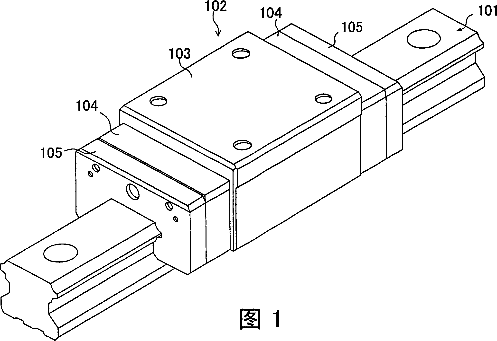
[0050] Embodiments of the present invention will be described below with reference to the drawings. 5 to 8 are diagrams showing the structure of the guiding device of the present invention, and FIG. 5 is an external perspective view, Image 6 It is the A-A sectional view of Fig. 5, Figure 7 It is a top view of the moving block, and Fig. 8 is an exploded perspective view of the moving block. 11 is a guide rail, and the guide rail 11 is formed with a plurality of (four in the figure) rolling grooves 12-1 to 12-4 for rolling bodies (balls) in the longitudinal direction.

[0051] 20 is a moving block freely assembled on the guide rail 11. The structure of the moving block 20 is to have a moving block main body 21, side covers 22 / 22 installed at both ends of the moving direction of the moving block main body 21, and mounted on the side cover 22. The lubricating device 23 / 23 on the outside of the moving direction of / 22, the end seal 24 / 24 installed on the outside of the moving d...


PUM


Abstract

A guiding device where foreign objects do not enter from gaps into a moving block even in an environment where a large amount of dust is present in the air, the gaps being formed by side faces of a track rail and inner faces of a moving block. A guiding device has a track rail and a moving block (20) and is constructed such that the moving block (20) is assembled so as to be movable relative to the track rail with rolling bodies that circulate in rolling body circulation paths in between. Foreign object entry prevention plates (34) are provided in the guiding device, and head ends of the plates are in contact with side faces of the track rail along its length direction. The plate (34) closes at least gaps formed by inner faces of skirt sections on both sides of the moving body (21) of the moving block (20), side-lid inner faces, and track rail side faces.

Description

technical field [0001] The present invention relates to a guide device including a guide rail and a moving block assembled on the guide rail freely through the movement of a rotating body, and particularly relates to a guide device suitable for use in an environment where fine dust is scattered. Background technique [0002] As shown in Figure 1, there is a device that is freely assembled on the guide rail 101 through the relative movement of a plurality of rotating bodies (balls or rollers) (including the situation when the guide rail 101 is fixed and the moving block 102 moves, and the moving block 102 is fixed and the guide rail 101 moves). Guide device on the mobile block 102 . The structure of this guide device is that the moving block 102 has a moving block main body 103 mounted on the guide rail 101 in a straddling state, side covers 104 / 104 installed on both ends of the relative moving direction in a state straddling the guide rail 101, and The state of 101 is insta...

Claims


Application Information

Patent Timeline
IPC IPC(8): F16C25/08F16C29/06F16C29/08
CPCF16C29/0647F16C29/086F16C29/088
Inventor 道冈英一八代大辅齐藤圭昭
Owner THK CO LTD
Why Eureka
Try Eureka