
Liquid crystal display unit and driving method therefor and drive device for liquid crystal display panel

A technology of a liquid crystal display device and a driving method, which is applied to static indicators, instruments, etc., can solve the problems of reducing the polarity inversion frequency and prolonging the flickering period, and achieves the effects of reducing power consumption and preventing flickering

Inactive Publication Date: 2006-11-15
SANYO ELECTRIC CO LTD
View PDF0 Cites 17 Cited by
  • Summary
  • Abstract
  • Description
  • Claims
  • Application Information

AI Technical Summary

Problems solved by technology

In addition, in the polarity inversion of the field cycle, the transmittance fluctuation at a frequency of about 30 Hz corresponding to the block frequency as described above occurs, and there is a high possibility that flicker can be confirmed.
Therefore, in general display modes requiring high display quality, no attempt has been made to reduce the polarity inversion frequency
[0015] In addition, in the conventional LCD, once the display voltage Vp of the same polarity is applied for more than two field periods, the residual DC (direct current voltage) portion applied to the liquid crystal layer is very large, so even if the corresponding voltage that should be applied to the liquid crystal is applied, Even if the display voltage Vp of the displayed content is applied to the pixel electrode, it cannot be properly displayed. In addition, the residual DC also causes the problem of prolonging the blinking period.

Method used


Image

  • Liquid crystal display unit and driving method therefor and drive device for liquid crystal display panel
  • Liquid crystal display unit and driving method therefor and drive device for liquid crystal display panel
  • Liquid crystal display unit and driving method therefor and drive device for liquid crystal display panel

Examples


Embodiment Construction

[0048] Preferred embodiments of the present invention (hereinafter referred to as embodiments) will be described below with reference to the drawings.

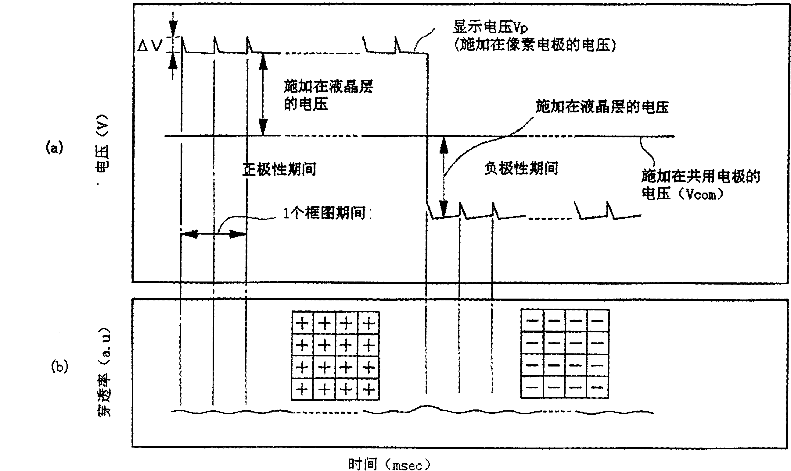
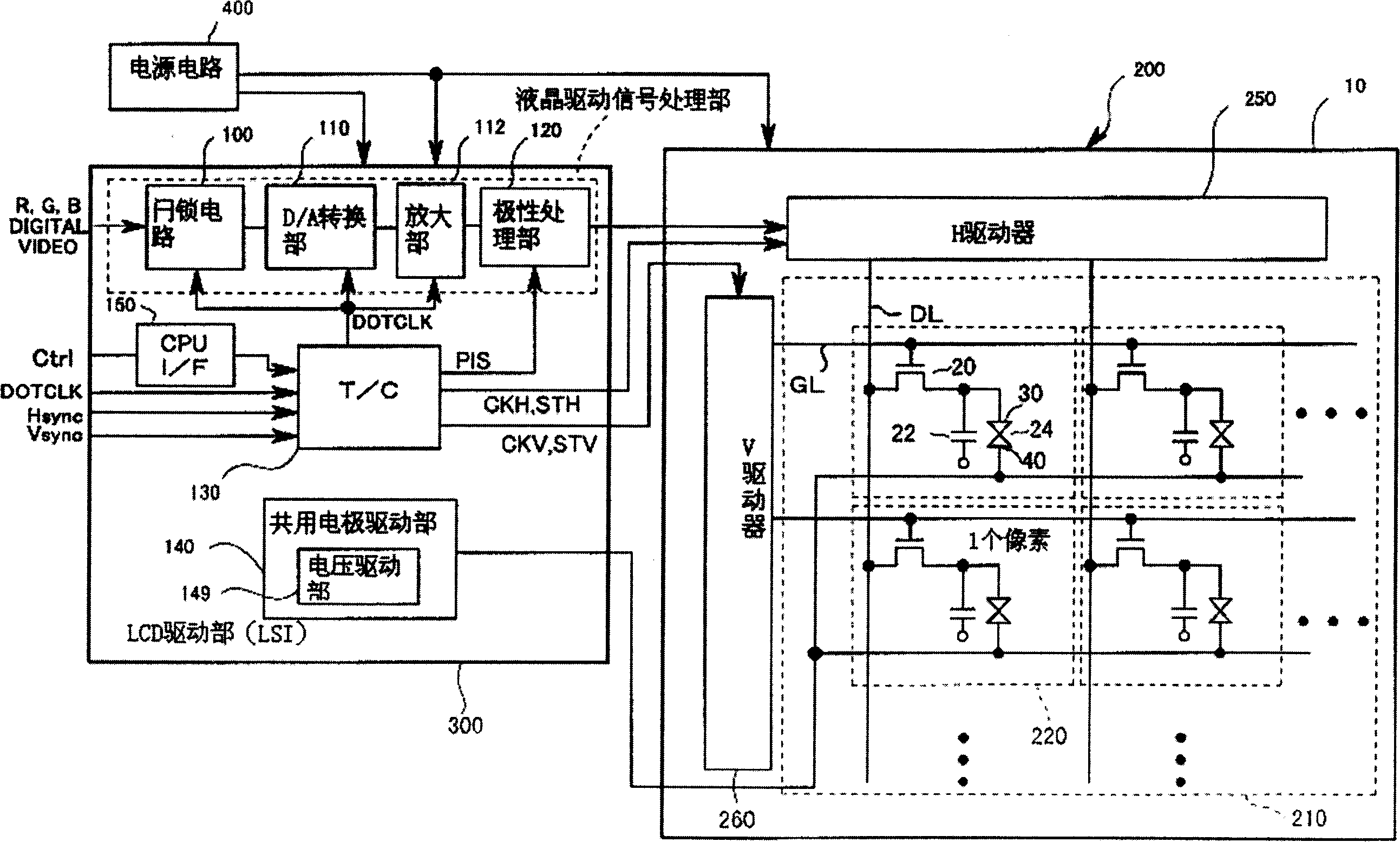
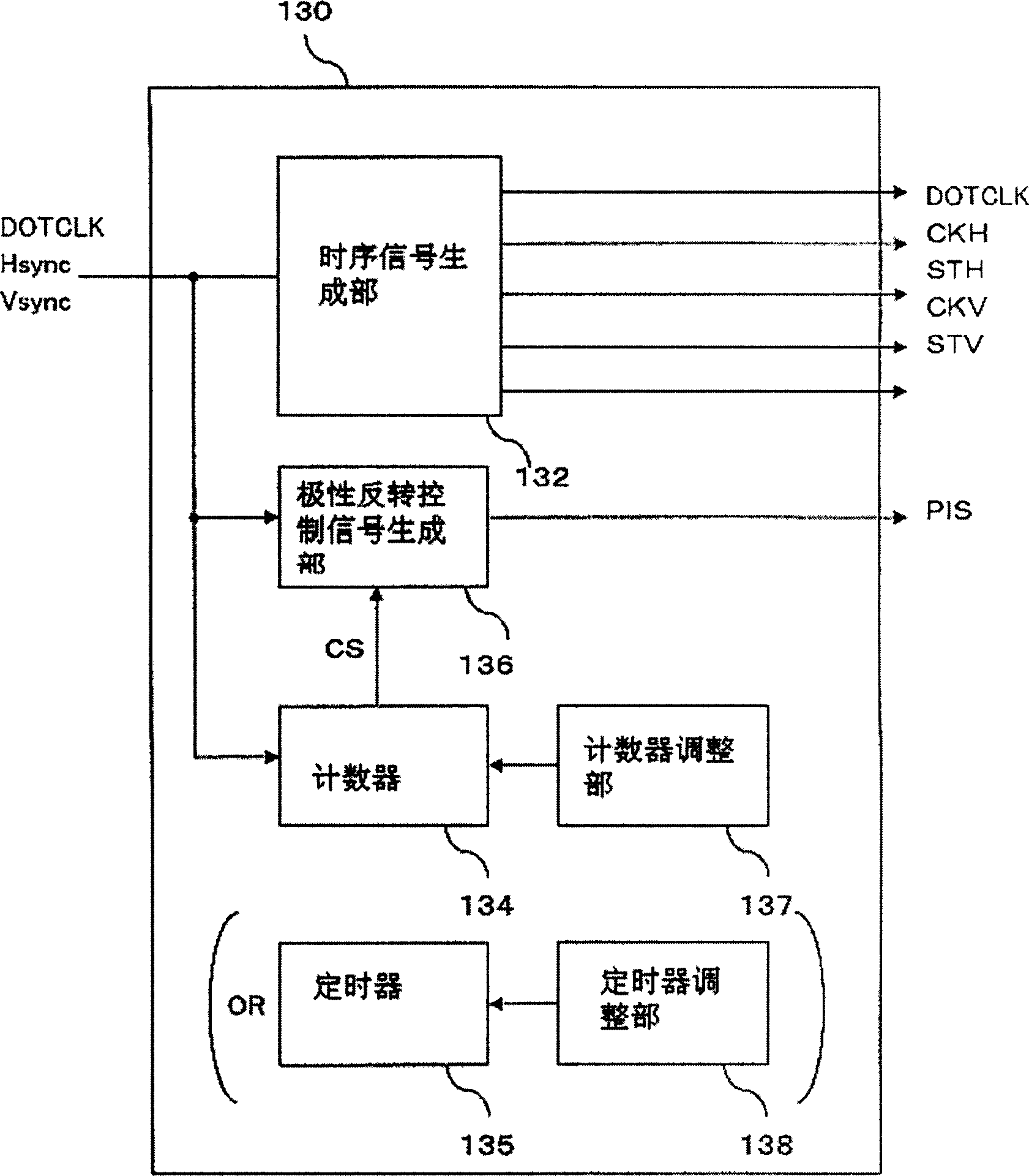
[0049] In the LCD according to the present embodiment, the polarity inversion period with respect to the reference value of the liquid crystal drive voltage is set to a period equal to or longer than two block periods. Making all the pixels constituting one screen have the same polarity means inverting the polarity for each screen, and the pixel polarity in one screen as described above is not implemented for each line or for each pixel. There are different line inversions or dot inversions etc. In addition, such polarity inversion driving is not limited to active-matrix LCDs equipped with switches such as TFTs in each pixel, but can also be applied to simple matrix-type LCDs that do not have switches. In the following, the display quality is better. , especially an active matrix LCD with better animation display quality than...


PUM


Abstract

The polarity inversion cycle of a voltage applied to a liquid crystal layer is set to at least 2-frame cycle, or more preferably to as long as about 10 sec. Accordingly, a flicker that could not have been prevented at a polarity inversion cycle of about one frame can be prevented, and a longer inversion cycle can reduce power consumption. A material low in ion reactivity and small in residual polarization is used as a liquid crystal material or an orientation film material, thereby preventing the occurrence of a residual DC component in a liquid crystal layer and the deterioration of display quality despite a longer polarity inversion cycle. In the case of an LCD provided with a minimal transmittance with respect to an applied voltage, black can be accurately displayed by, for example, regulating a common electrode potential so that an applied voltage at which the transmittance of a liquid crystal shows a minimum value during an anodic application period is equal to that during a cathodic application period.

Description

technical field [0001] The present invention relates to a liquid crystal display device, in particular to the polarity inversion of the voltage applied to the liquid crystal layer. Background technique [0002] Liquid crystal display devices that can be thin, light, small and low power consumption are currently used as displays for various devices. This liquid crystal display device (hereinafter referred to as LCD (Liquid Crystal Display)) has a structure in which liquid crystal is sealed and laminated between two substrates with electrodes provided on opposite surfaces, and a voltage signal is applied between the electrodes, Display is performed by controlling the orientation of liquid crystals whose optical characteristics vary depending on the orientation state, and controlling the transmittance of light from the light source. [0003] Here, if a DC voltage is continuously applied between the electrodes provided on opposite sides of the substrate, the alignment state of ...

Claims


Application Information

Patent Timeline
IPC IPC(8): G02F1/133G09G3/20G09G3/36
Inventor 小间德夫
Owner SANYO ELECTRIC CO LTD
Features
  • Generate Ideas
  • Intellectual Property
  • Life Sciences
  • Materials
  • Tech Scout
  • Unparalleled Data Quality
  • Higher Quality Content
  • 60% Fewer Hallucinations
Learn More