Combined wood planing machine

A woodworking planer and plane planer technology, which is applied in the direction of planer, fine planer, etc., can solve the problems of increased manufacturing cost, high production cost, inconvenient use, etc.

Inactive Publication Date: 2006-11-22
叶伟豪
View PDF1 Cites 6 Cited by
  • Summary
  • Abstract
  • Description
  • Claims
  • Application Information

AI Technical Summary

Problems solved by technology

[0002] Woodworking planer is a processing machine that uses a planer to plan wood. According to different requirements, woodworking planer can be divided into planer and pressure planer. Its function is single
During the planing process, the wood is pushed by hand for planing; during the planing process, the wood is sent to the roller to be automatically fed for planing. When both planing and pressing are required, two

Method used


Image

  • Combined wood planing machine
  • Combined wood planing machine
  • Combined wood planing machine

Examples


Embodiment Construction

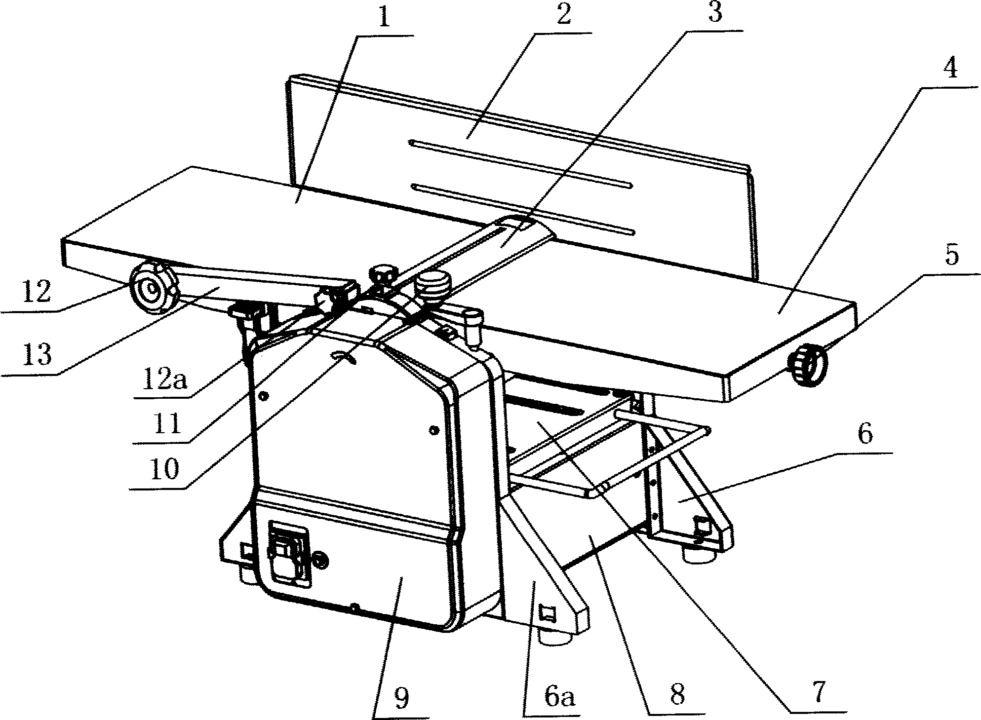
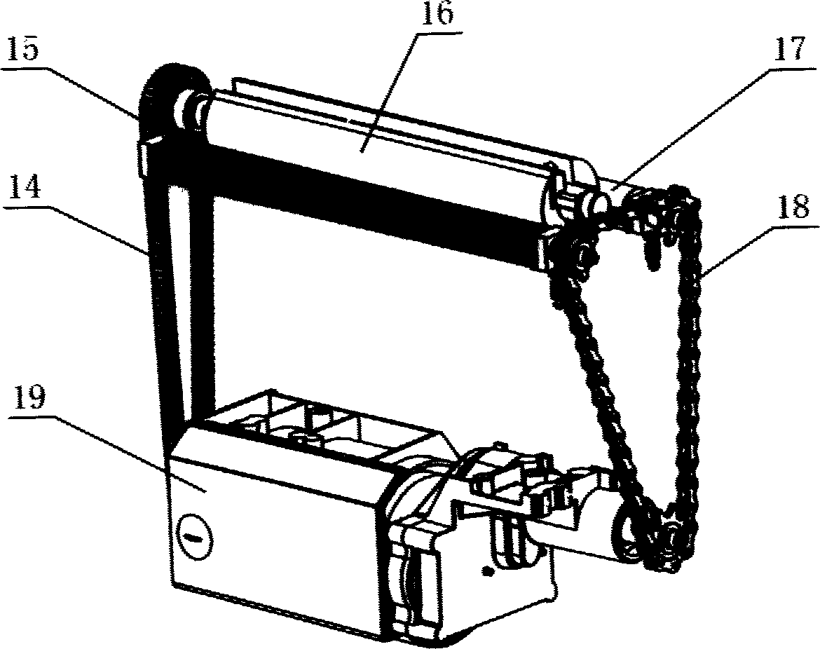
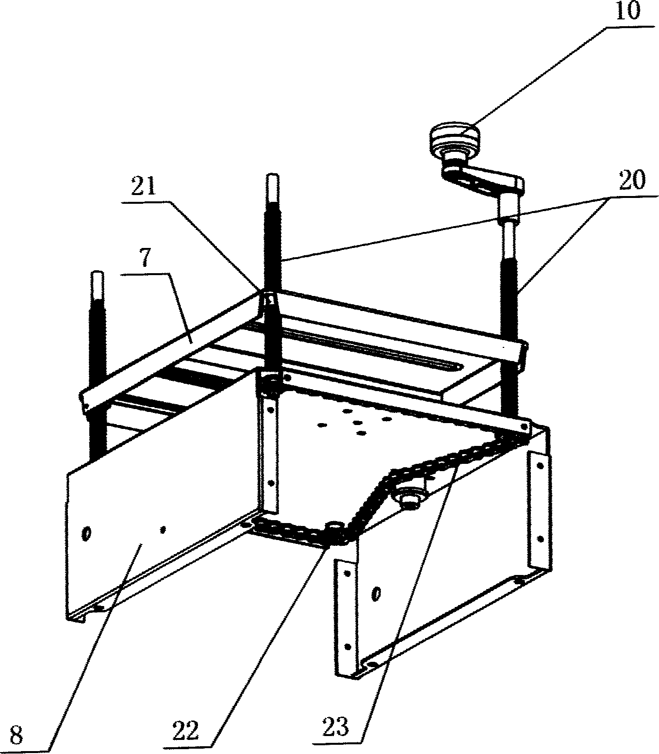
[0016] As shown in the figure, the left side plate 6a and the upper part of the right side plate 6 are connected with a planing workbench composed of a fixed workbench 1 and a movable workbench 4, and a cutter shaft 16 is arranged between the fixed workbench 1 and the movable workbench 4. The front roller 15 and the rear roller 17 are arranged respectively on both sides of the cutter shaft 16, and the front roller 15 and the rear roller 17 cooperate with the output shaft transmission at one end of the motor 19 arranged in the left side plate 6a and the bottom base 8 of the right side plate 6. , the output shaft at the other end of the motor 19 is in transmission cooperation with the cutter shaft 16. The output shaft at one end of the motor 19 is shifted to a relatively reasonable feed speed through the gear, and then the front roller shaft 15 and the rear roller shaft 17 are driven to rotate through the transmission of the chain 18, and the output shaft at the other end is driv...


PUM


Abstract

The invention relates to a combined woodworking planer, which is characterized in that: the upper parts of left and right side plates are connected to the plane platform that formed by fixed platform and movable platform; the blade axle is arranged between the fixed and movable platforms; two sides of blade axle are arranged with front and back rolling axles which are geared with one output axle of motor at the lower part of left and right side plates; another output axle of motor is geared with the blade axle; the thickness platform is arranged under the plane platform; the thickness platform via one group of lead screw is matched with the base at the lower part of it; the lower ends of said lead screws are geared matched via transmission chains. The inventive combined woodworking planer has simple structure, with plane and thickness functions, to reduce the cost and save resource.

Description

technical field [0001] The invention belongs to the technical field of woodworking machinery, and its body is a combined woodworking planer. Background technique [0002] A woodworking planer is a processing machine that uses a planer to plan wood. According to different usage requirements, a woodworking planer can be divided into a planer and a planer, and its function is single. During the planing process, the wood is pushed by hand for planing; during the planing process, the wood is sent to the roller to be automatically fed for planing. When both planing and pressing are required, two machines are required. It is inconvenient to use, and increases the manufacturing cost, resulting in waste of resources. After patent retrieval, it was found that the application number: 01216235.3, name: technical scheme of woodworking planer and planer combination machine tool, the protection point is mainly on the circuit control structure, its mechanical s...

Claims


Application Information

Patent Timeline
IPC IPC(8): B27C1/06
Inventor 叶伟豪
Owner 叶伟豪
Why Eureka
Try Eureka