Sheet feeding device and image forming apparatus

A paper conveying and paper technology, applied in the field of image forming devices, can solve the problem that the paper loading capacity of the main bottom plate and the sub bottom plate cannot be guaranteed, etc.

Inactive Publication Date: 2006-11-22
CANON KK
View PDF4 Cites 9 Cited by
  • Summary
  • Abstract
  • Description
  • Claims
  • Application Information

AI Technical Summary

Problems solved by technology

Therefore, if the spring characteristics of the springs of the main chassis and the sub-chassis deviate, the paper loading capacity on the main

Method used


Image

  • Sheet feeding device and image forming apparatus
  • Sheet feeding device and image forming apparatus
  • Sheet feeding device and image forming apparatus

Examples


no. 1 approach

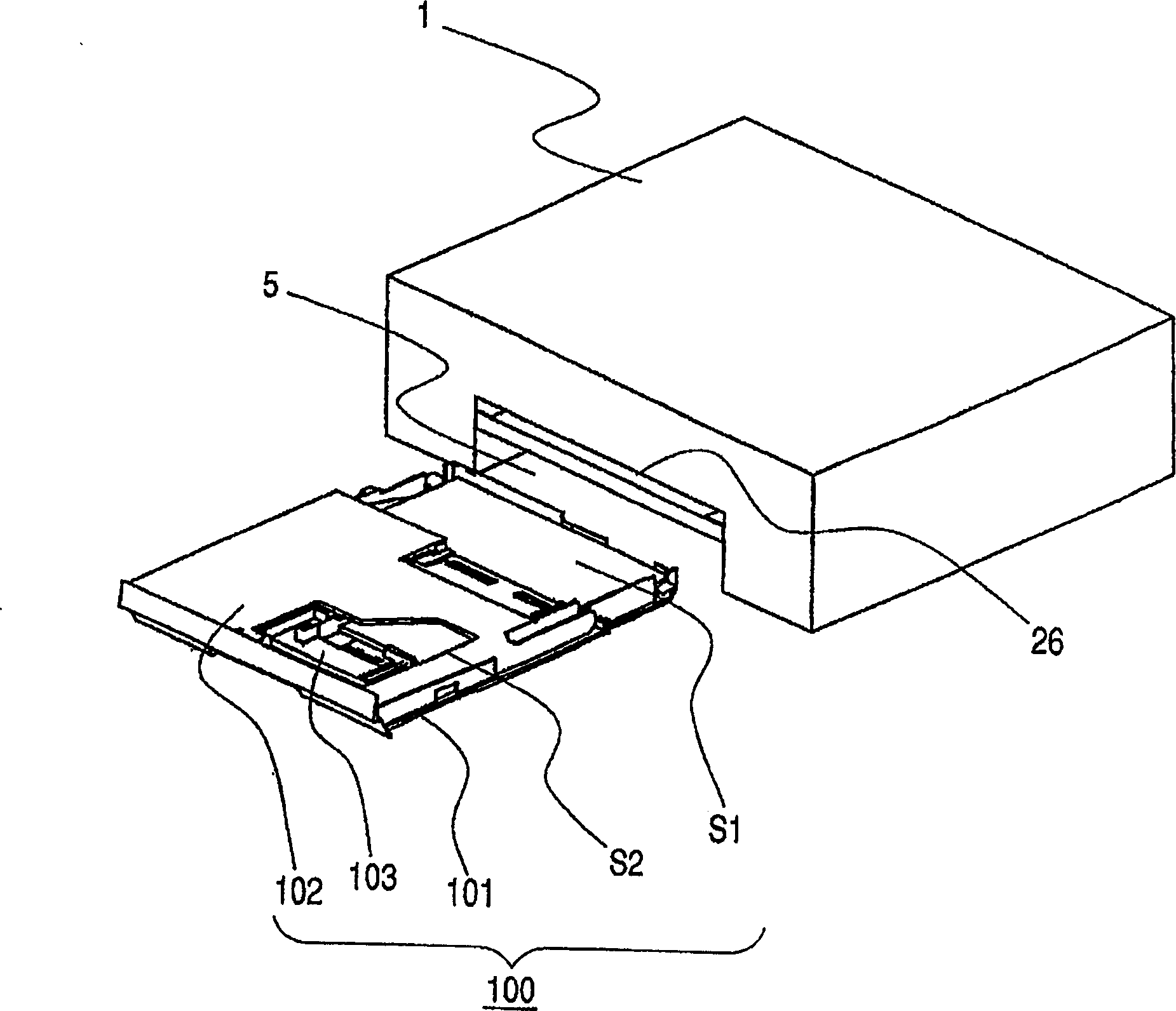
[0033] Such as figure 1 As shown, the paper feeding cassette (paper storage unit) 100 constituting the paper conveying device can be attached or detached from the cassette insertion opening 5 opened on the front surface of the printer main body 1 with the paper S stored therein. The printed paper S is discharged from the paper discharge port 26 .

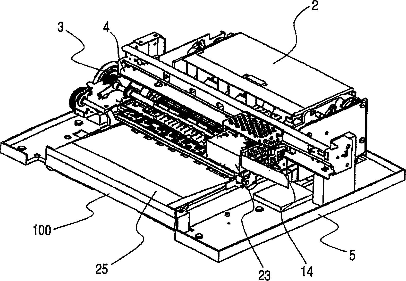
[0034] of the internal structure of the printer body 1 figure 2 Among them, there is a paper feeding unit 2 constituting a paper feeding device together with a detachable paper feeding cassette 100 below the mechanical part, and the paper S fed from the paper feeding cassette 100 is sent to the LF unit 3 . The CR unit 4 has a carriage 14 on which a recording head 23 for printing is mounted, and is a mechanism for reciprocating the carriage 14 in the sub-scanning direction of the sheet S. As shown in FIG. The paper feeding unit 2 and the CR unit 4 have their own independent drive motors, and work together to perform printing opera...

no. 2 Embodiment approach

[0055] Figure 14 A second embodiment that can also be called an application example of the above-mentioned first embodiment is shown. In the configuration shown in the first embodiment, the cover 102 is rotated about the pin shaft 102a, and can be removed from the standing posture substantially perpendicular to the main case 101 . On the other hand, in this second embodiment, the structure is a structure in which the cover 102 is lifted up vertically and removed from the state where the main case 101 is blocked. Thus, the main box 101 and the sub-box 103 are stacked vertically, the cover 102 is positioned on the main box 101 by the position pin 101d, and the cover body does not move when the sub-box 103 is moved. Therefore, in this second embodiment, when the paper feeding cassette 100 is taken out from the printer main body 1, the cover 102 can be easily detached from the main cassette 101, and the work when replenishing the main cassette 101 with paper S1 can be improved. ...

no. 3 Embodiment approach

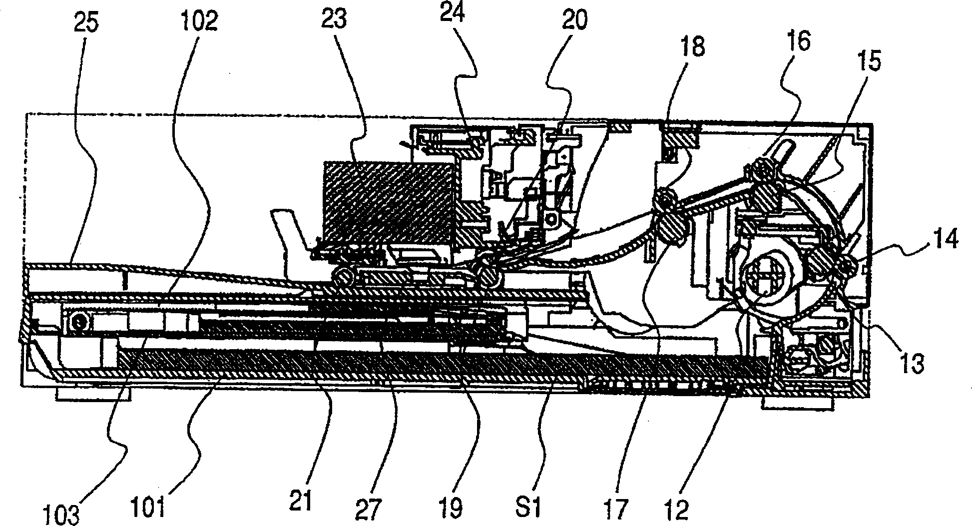
[0063] the following, Figure 15 ~ Figure 18 3rd embodiment is shown. In addition, the same code|symbol is attached|subjected to the same or common member as the member shown in 1st, 2nd embodiment, and the description of the overlapping part is abbreviate|omitted.

[0064] Such as Figure 15 As shown, the paper discharge tray 200 for stacking the paper S discharged after being printed in the printer main body 1 is arranged directly above the above-mentioned paper feeding cassette 100 . A paper discharge panel 199 a is provided, and the paper discharge panel 199 a also serves as a partition between the lower paper feeding cassette 100 and constitutes the paper discharge tray 200 . The paper discharge panel 199a is integrally formed, is provided on the frame base 202 of the printer main body 1, and is used for stacking the discharged paper S.

[0065] Figure 16 Indicates the paper feed path (paper transport path) during printing. The components and devices for picking up ...


PUM


Abstract

A paper conveying device includes a cassette-type paper storage unit that can be attached to or detached from an image forming apparatus main body in a state where paper is stored. Among them, the paper storage part has a main storage part and a sub storage part composed of a plurality of papers of different types and sizes at the same time. Paper can be conveyed from the sub storage unit in a state where the paper storage unit is attached to the main body of the image forming apparatus. In inkjet printers, etc., in order to reduce the burden on the user when replacing paper, especially for paper that is prone to curling such as postcards, the necessary space is ensured even if the drop to the loading surface of the paper discharge tray is not considered as a curled portion. Stack up space. Therefore, it is easy to adopt such a device as a low-cost model for general consumers, which suppresses the increase in size and manufacturing cost of the device.

Description

technical field [0001] The present invention relates to image forming apparatuses such as copiers, facsimile apparatuses, and printers, and to a paper conveying device equipped in the image forming apparatuses for conveying a paper-like recording medium (hereinafter referred to as paper) to an image forming unit. Background technique [0002] In an inkjet recording device which is a field of image forming apparatuses, a paper conveying device for conveying paper to a mechanical part for printing uses an automatic paper feed (ASF) method or a paper cassette method to convey paper. In the ASF method, paper directly stored in the main body of the recording device is fed out, and in the paper feeder system, the paper is attached to or detached from the main body of the recording device in a state where the paper is stored. In addition, recently, a paper conveying device that combines these ASF systems and paper feeding cassette systems has also been put into practical use. In p...

Claims


Application Information

Patent Timeline
IPC IPC(8): B65H1/04B65H1/00B65H31/18
Inventor 仓田哲治山本恒介吉川淳一平井康行风村美隆
Owner CANON KK
Why Eureka
Try Eureka