Oven utensil
A technology for stoves and furnaces, which is applied to home appliances, furniture parts, household stoves/stoves, etc., can solve the problems that capacitive touch switches or infrared sensing touch switches cannot be used, and achieve good appearance and high operability , The effect of comfortable touch operation
- Summary
- Abstract
- Description
- Claims
- Application Information
AI Technical Summary
Problems solved by technology
Method used
Image

Examples
Embodiment Construction
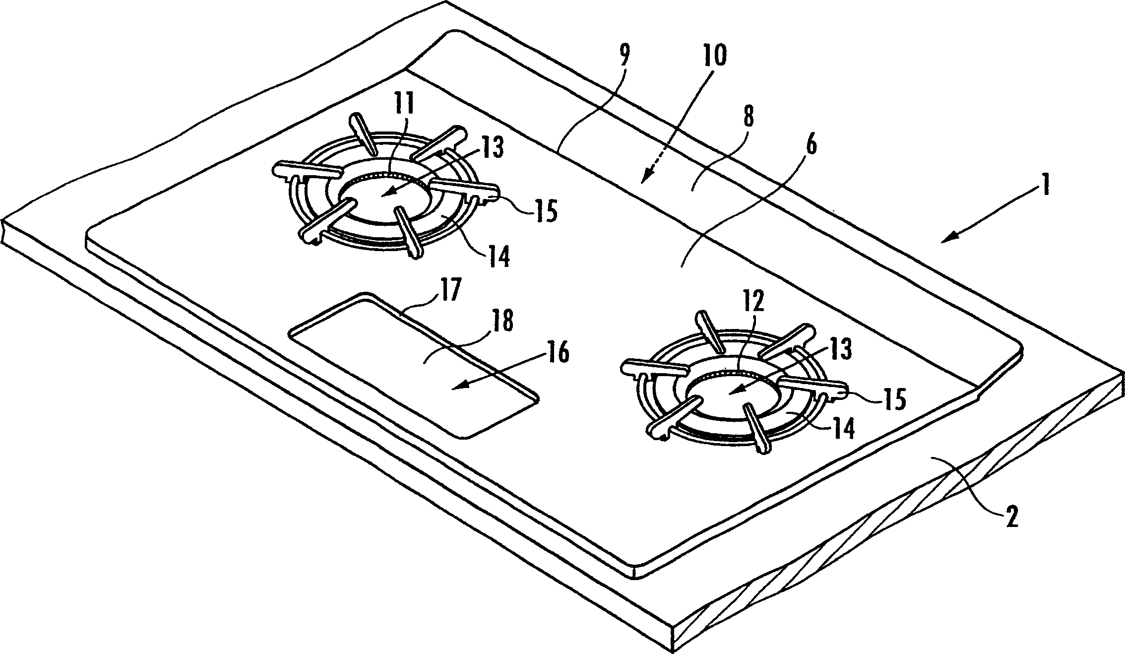
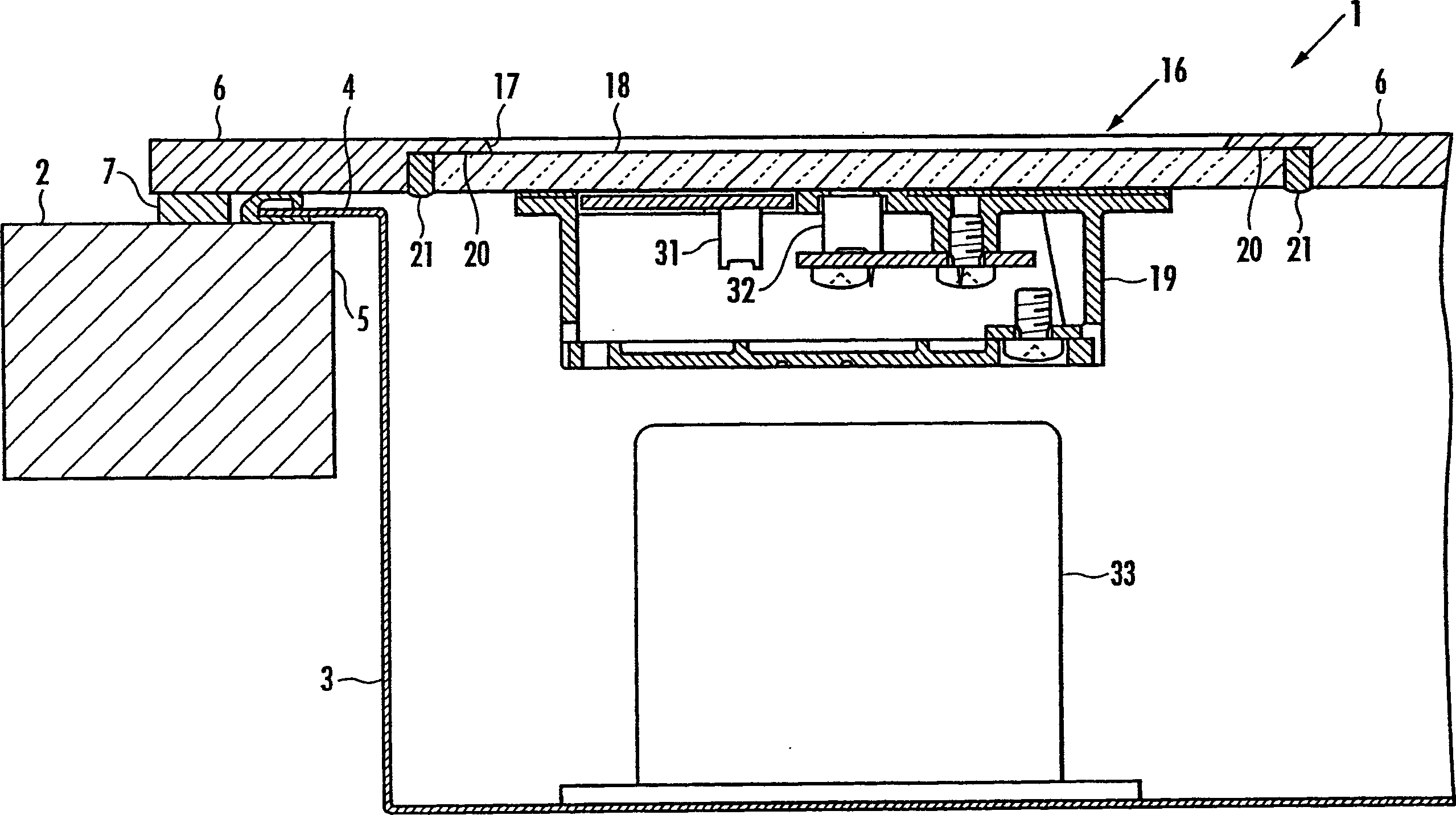
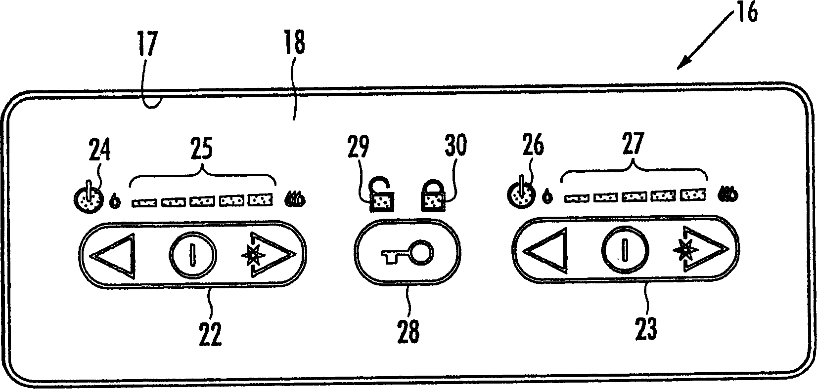
[0022] One embodiment of the present invention will be described with reference to the drawings. figure 1 A perspective view showing a stove in one embodiment of the present invention, figure 2 A schematic cross-sectional view showing the operating part and its vicinity, image 3 A plan view of the operation unit is shown, and a schematic cross-sectional view of another embodiment of the panel is shown in FIG. 4 .
[0023] The stove 1 of the present embodiment is as figure 1 As shown, it is set on the countertop 2 of the kitchen system. Such as figure 2 As shown in the middle part, the upper part of the stove main body 3 is open, and the stove main body 3 is fixed to the periphery of the stove installation opening 5 formed by locking the flange 4 formed on the periphery of the stove body to the table top 2. , and is set at the opening 5 for setting the stove.
[0024] The panel 6 of the stove 1 is as image 3 As shown, it is exposed on the table top 2. The panel 6 is ...
PUM
 Abstract
Description
Claims
Application Information
 - Generate Ideas
- Intellectual Property
- Life Sciences
- Materials
- Tech Scout
- Unparalleled Data Quality
- Higher Quality Content
- 60% Fewer Hallucinations
Browse by: Latest US Patents, China's latest patents, Technical Efficacy Thesaurus, Application Domain, Technology Topic, Popular Technical Reports.
© 2025 PatSnap. All rights reserved.Legal|Privacy policy|Modern Slavery Act Transparency Statement|Sitemap|About US| Contact US: help@patsnap.com