Heat radiator, auxiliary jig and heat radiator manufacturing method

A technology of heat dissipation device and manufacturing method, which is applied in cooling/ventilation/heating transformation, instrumentation, electrical digital data processing, etc., and can solve problems such as reduced heat dissipation efficiency, poor fin uniformity, and poor parallelism

Inactive Publication Date: 2006-11-22
THERMAL TECH
View PDF1 Cites 7 Cited by
  • Summary
  • Abstract
  • Description
  • Claims
  • Application Information

AI Technical Summary

Problems solved by technology

[0005] Although the above-mentioned prior art (Patent No. tw569660 of Taiwan Province of China) can achieve the purpose of simple manufacturing process and cost reduction, it is necessary to apply heavy pressure to both ends of the base in the manufacturing process to deform the groove and clamp the fin If the step of fins is applied to a radiator with a high height, the fins will be deflected because there is no supporting point on the top edge of the fins, resulting in poor uniformity and poor parallelism of the fins, especially the higher the height of the fins. When the temperature is high, the problem is more serious, which in turn causes the airflow to be uneven when the cooling device is in use, and the heat dissipation efficiency is reduced

Method used


Image

  • Heat radiator, auxiliary jig and heat radiator manufacturing method
  • Heat radiator, auxiliary jig and heat radiator manufacturing method
  • Heat radiator, auxiliary jig and heat radiator manufacturing method

Examples


Embodiment Construction

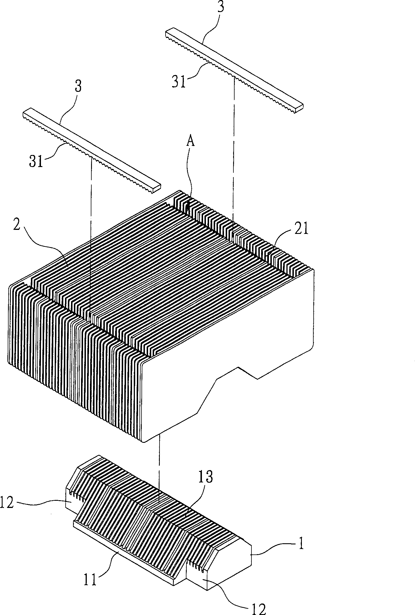
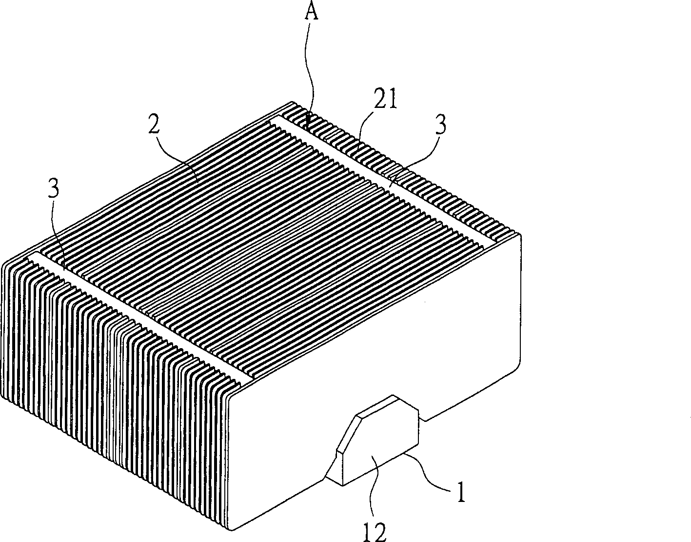
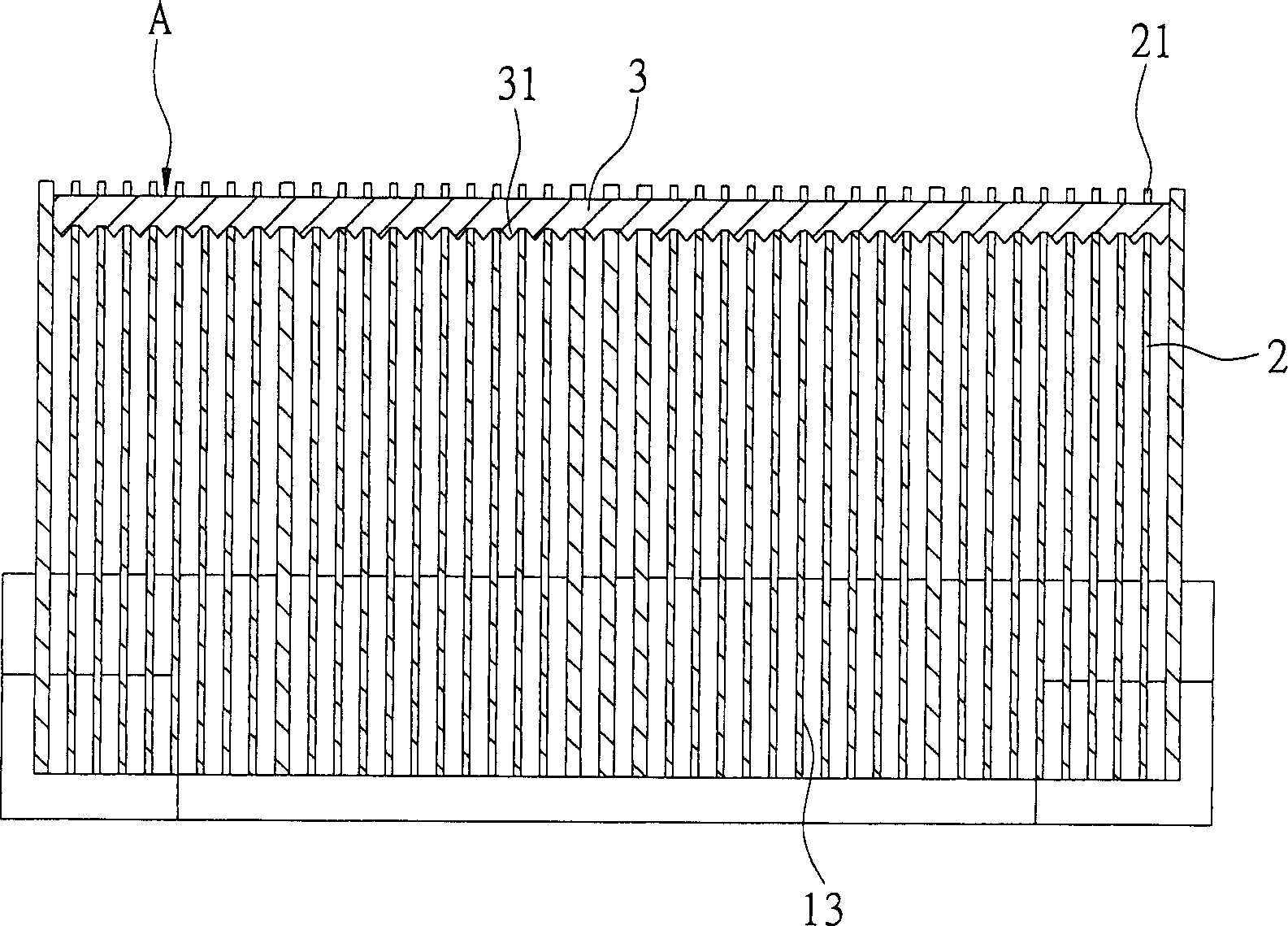
[0019] see Figure 1 to Figure 3 , the present invention is to provide a heat sink that can produce better parallelism, which includes a base 1, a plurality of fins 2 and at least one support device 3, wherein the base 1 is made of copper or aluminum and other thermal conductivity It is made of good metal material. In this embodiment, the base 1 includes a central section 11 and wing sections 12 respectively extending from two corresponding sides of the central section 11 . The base 1 is provided with a plurality of parallel grooves 13, and the plurality of grooves 13 are equidistantly arranged on the central section 11 and the wing section 12, and the top edge and two ends of each groove 13 are open. shape, which is convenient for assembling the plurality of fins 2 described above.

[0020] The plurality of fins 2 are sheets, and the plurality of fins 2 are made of metal materials with good thermal conductivity such as copper or aluminum, and the top edges of the plurality o...


PUM


Abstract

The invention discloses a manufacturing method of radiating device and auxiliary treating device with support device and radiating device with better leveling degree, which comprises the following steps: setting multiple locating grooves on the bottom brink of support device to chuck multiple fin apical margins; supplying support for device and base; pressing heavy pressure on two ends of base to clamp fin; making fin possess excellent flatness; producing even air-flow and excellent radiation efficiency for radiation device.

Description

technical field [0001] The invention relates to a heat dissipation device capable of producing better parallelism, an auxiliary jig and a manufacturing method of the heat dissipation device, especially a method that can provide good support for the top edge of the fins so that the fins will not be deflected and the fins The invention provides a cooling device, an auxiliary jig and a manufacturing method for the cooling device with good sheet uniformity and good parallelism, thereby making the air flow more uniform and the heat dissipation efficiency better. Background technique [0002] With the rapid development of the computer industry, the execution speed of heat sources such as chips and central processing units (CPU) is getting faster and faster, and the relative heat generation of heat sources is also getting higher and higher. In order to discharge the high temperature generated by heat sources in Externally, to make the heat source operate normally at the allowable t...

Claims


Application Information

Patent Timeline
Patent Type & Authority Applications(China)
IPC IPC(8): H01L23/34G06F1/20H05K7/20
Inventor 夏明宏
Owner THERMAL TECH
Why Eureka
Try Eureka