Liquid crystal display unit set
A liquid crystal display module and display surface technology, applied in static indicators, optics, instruments, etc., can solve the problems of deformation and fracture of the front wall, and achieve the effect of easy implementation
- Summary
- Abstract
- Description
- Claims
- Application Information
AI Technical Summary
Problems solved by technology
Method used
Image

Examples
no. 1 example
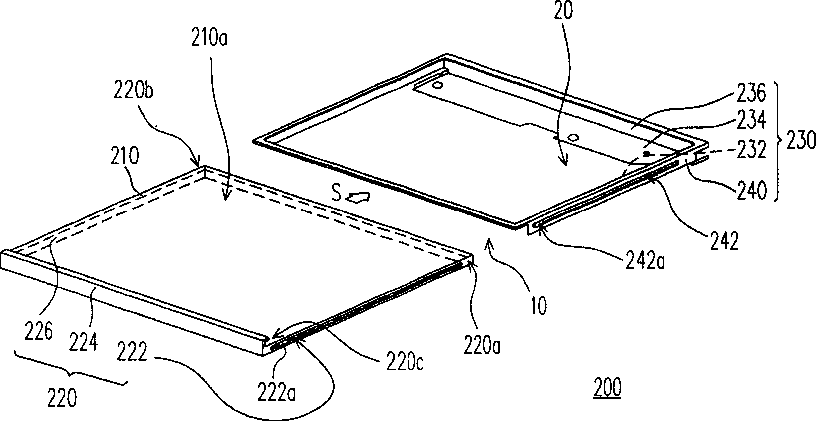
[0048] Figure 2A Shown is a schematic diagram of the assembly method of the liquid crystal display module of the first embodiment of the present invention, please refer to Figure 2A shown. The liquid crystal display module 200 of this embodiment includes a liquid crystal panel 210 , a backlight module 220 , and a frame 230 . Wherein, the liquid crystal panel 210 has a display surface 210a, and the backlight module 220 has at least two first sliding guide portions 222 . In general, the backlight module 220 may further include a frame 224 and a side light source 226 . The frame 224 is suitable for supporting the liquid crystal panel 210 and the surface light source 226 , and the material of the frame 224 is plastic, metal or plastic steel, and the first sliding guide part 222 can be formed on the frame 224 , for example. Alternatively, each first sliding guide portion 222 is formed on the two side walls ( 220 a and 220 b ) of the backlight module 220 itself.
[0049] In ad...
no. 2 example
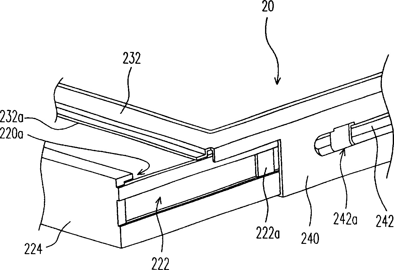
[0060] image 3 A partial schematic diagram showing the assembly of the liquid crystal display module according to the second embodiment of the present invention, please refer to image 3 . This embodiment is similar to the first embodiment, the main difference is that: the first sliding guiding part 322 of this embodiment is a flange, and the second sliding guiding part 342 is a slide groove. In addition, the sliding guiding side plate 340 has a locking hole 342a located in the sliding groove, and the frame 324 has an engaging hole 322a corresponding to the locking hole 342a. The design method of this embodiment can obtain the same effect as that of the first embodiment.
[0061] In summary, the liquid crystal display module of the present invention has at least the following advantages:
[0062] 1. The liquid crystal display module of the present invention has a sliding guide side plate, and the backlight module can be assembled with the outer frame by sliding in sideways...
PUM
 Abstract
Description
Claims
Application Information
 - R&D
- Intellectual Property
- Life Sciences
- Materials
- Tech Scout
- Unparalleled Data Quality
- Higher Quality Content
- 60% Fewer Hallucinations
Browse by: Latest US Patents, China's latest patents, Technical Efficacy Thesaurus, Application Domain, Technology Topic, Popular Technical Reports.
© 2025 PatSnap. All rights reserved.Legal|Privacy policy|Modern Slavery Act Transparency Statement|Sitemap|About US| Contact US: help@patsnap.com