Diffraction element and optical disk device

A diffractive element, center position technology, applied in beam guiding device, optical recording head, recording/reproducing with optical method, etc., can solve problems such as inability to prevent astigmatism

Inactive Publication Date: 2006-11-29
SANKYO SEIKI MFG CO LTD
View PDF1 Cites 0 Cited by
  • Summary
  • Abstract
  • Description
  • Claims
  • Application Information

AI Technical Summary

Problems solved by technology

[0005] However, in the case of the diffractive element described in Patent Document 1, since a considerable difference occurs in the phase of the main beam between the region having the groove portion and the flat portion where the groove portion is not formed, there is a problem that it cannot Prevent astigmatism

Method used


Image

  • Diffraction element and optical disk device
  • Diffraction element and optical disk device
  • Diffraction element and optical disk device

Examples


other Embodiment approach

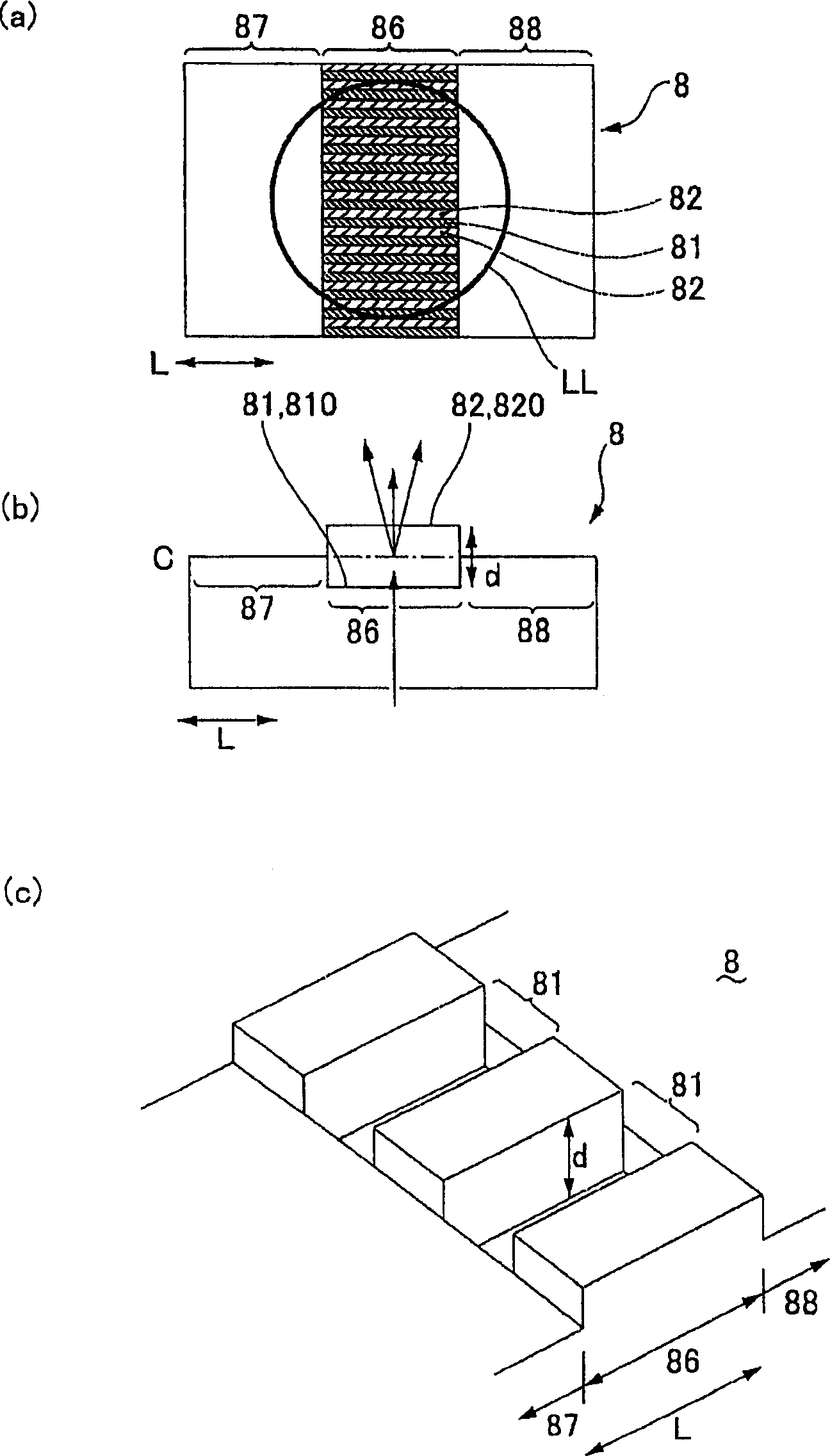
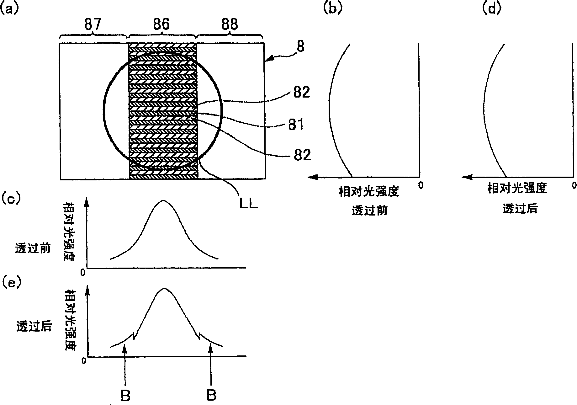
[0051] Figure 5 (a) and (b) are respectively a plan view of a diffraction element in another embodiment 1; and a cross-sectional view when the diffraction element is cut along the longitudinal direction of the groove portion. in addition, Figure 6 (a) and (b) are respectively a plan view of a diffraction element according to another embodiment 2; and a cross-sectional view when the diffraction element is cut along the longitudinal direction of the groove portion. In Embodiments 1 and 2 described below, since the basic configuration is the same as that of Embodiment 1, common parts are described with the same reference numerals.

[0052] Such as Figure 5 (a), (b) and Figure 6 As shown in (a) and (b), in the optical disc device 1 of the other embodiments 1 and 2, as in the above-mentioned embodiment, a plurality of grooves and ridges are formed in the center of the diffraction element 8 and arranged alternately. The grid area 86 is formed, and the two sides of the grid a...


PUM

PropertyMeasurementUnit
wavelengthaaaaaaaaaa

Abstract

The invention provides a kind of diffraction components which use diffracted wave bundles and undiffracted wave bundles, abolish the offset of track and prevent the occurrence of astigmatism, and CD devices which use said diffraction components. Said diffraction components (8) have a number of furrows (81) and convexes (82) which are ranked alternately to a grid regional (86) correspondingly on the surface, while the both surface along the furrows (81) are smooth flat regions (87,88), which are located on the same height of the center of the furrows (81) in depth. Therefore, the furrows (81) are located on the area which is smaller than the section area of beam via setting diffraction components. Even as used as (3) fasciculated beam creating components, it also can prevent diffraction components (8) creating astigmatism, because the flat regions (87, 88) are located on the same height of the center of the furrows (81) in depth.

Description

technical field [0001] The present invention relates to a diffraction element in which grooves and ridges are alternately arranged, and an optical disc device having the diffraction element. Background technique [0002] Although various schemes have been proposed for the composition of the optical disc for signal detection, no matter what kind of construction is adopted, the optical disc device basically has: a laser light source; a photodetector; The incident light path and the optical system that guides the return light reflected on the optical disc to the return light path of the photodetector. In addition, various diffractive elements are used in optical disc devices. [0003] For example, a technology for canceling tracking bias by using diffracted light and non-diffracted light beams has been disclosed. In order to obtain tracking error signals by using DPP (Differential Push-pull), etc., the technology uses diffraction elements to obtain tracking error signals from ...

Claims


Application Information

Patent Timeline
Patent Type & Authority Applications(China)
IPC IPC(8): G11B7/135
CPCG11B7/1353G11B7/0903
Inventor 酒井博
Owner SANKYO SEIKI MFG CO LTD
Why Eureka
Try Eureka