Versatile and modular workpiece holding device

A technology for holding devices and workpieces, which is applied in the direction of grinding workpiece supports, maintenance and safety accessories, manufacturing tools, etc. It can solve problems such as difficult universal workpiece holding devices, and achieve the effects of optimizing acceleration, convenient operation, and avoiding play and deformation

Inactive Publication Date: 2006-11-29
COMAU SYST FRANCE
View PDF0 Cites 6 Cited by
  • Summary
  • Abstract
  • Description
  • Claims
  • Application Information

AI Technical Summary

Problems solved by technology

[0013] Another disadvantage of this implementation is that it is difficult to produce a universal workpiece holding device that can be adapted to several types of workpieces

Method used


Image

  • Versatile and modular workpiece holding device
  • Versatile and modular workpiece holding device
  • Versatile and modular workpiece holding device

Examples


Embodiment Construction

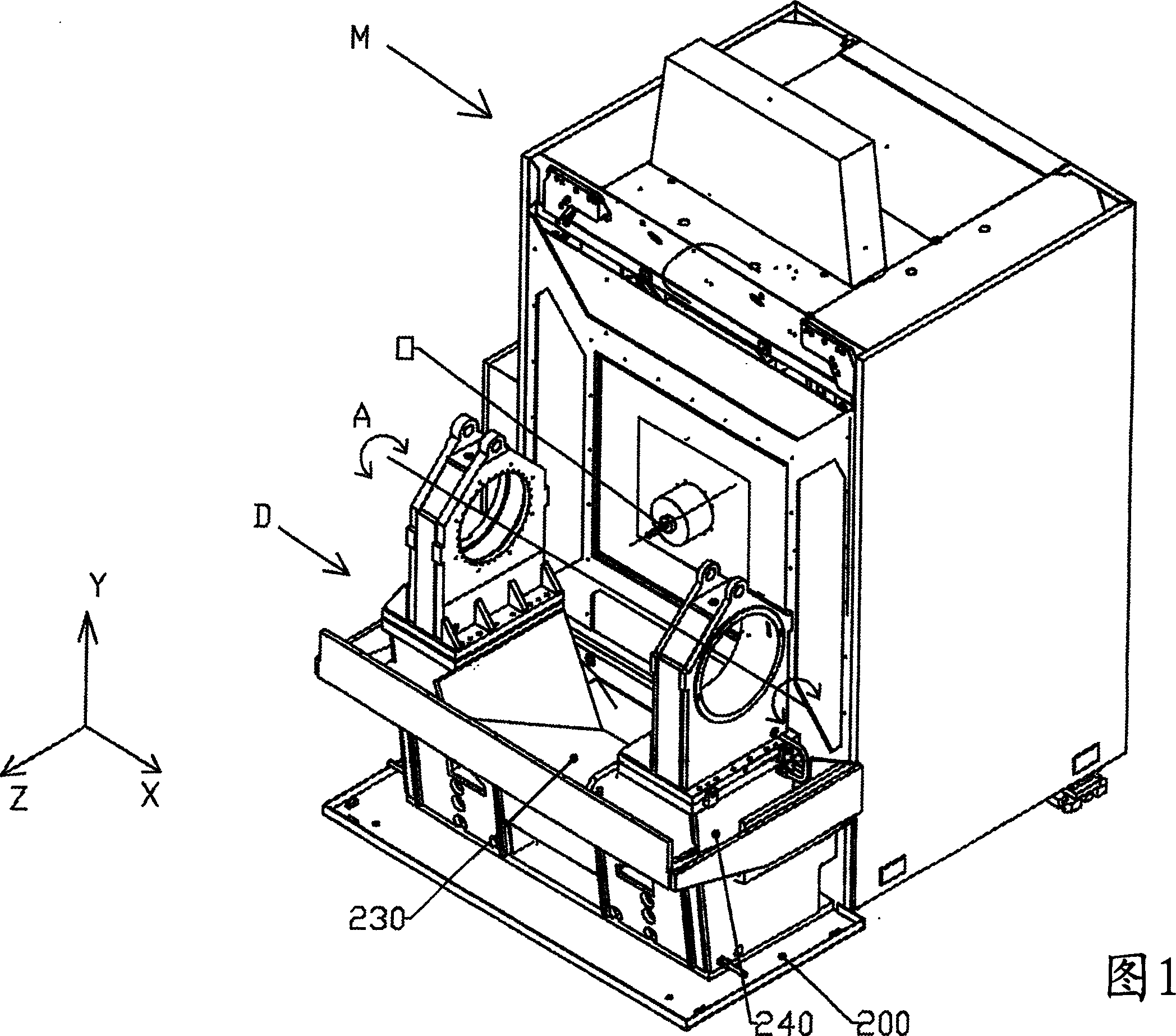
[0037] As shown in FIG. 1, the workpiece holding device generally designated D has a reference axis of rotation A which intersects the longitudinal axis Z of a tool O of a processing machine M associated with the device D . According to the illustrated but non-limiting embodiment, the machining machine M is a high-speed machining tool that provides actuation in three axes X, Y, Z along a sliding tool holder O. According to the non-limiting embodiment shown, said device D thus provides for the rotation of the workpiece (not shown) to be machined along a horizontal axis of rotation A intersecting the longitudinal axis of rotation Z of said tool O. Therefore, axis A is parallel to axis X.

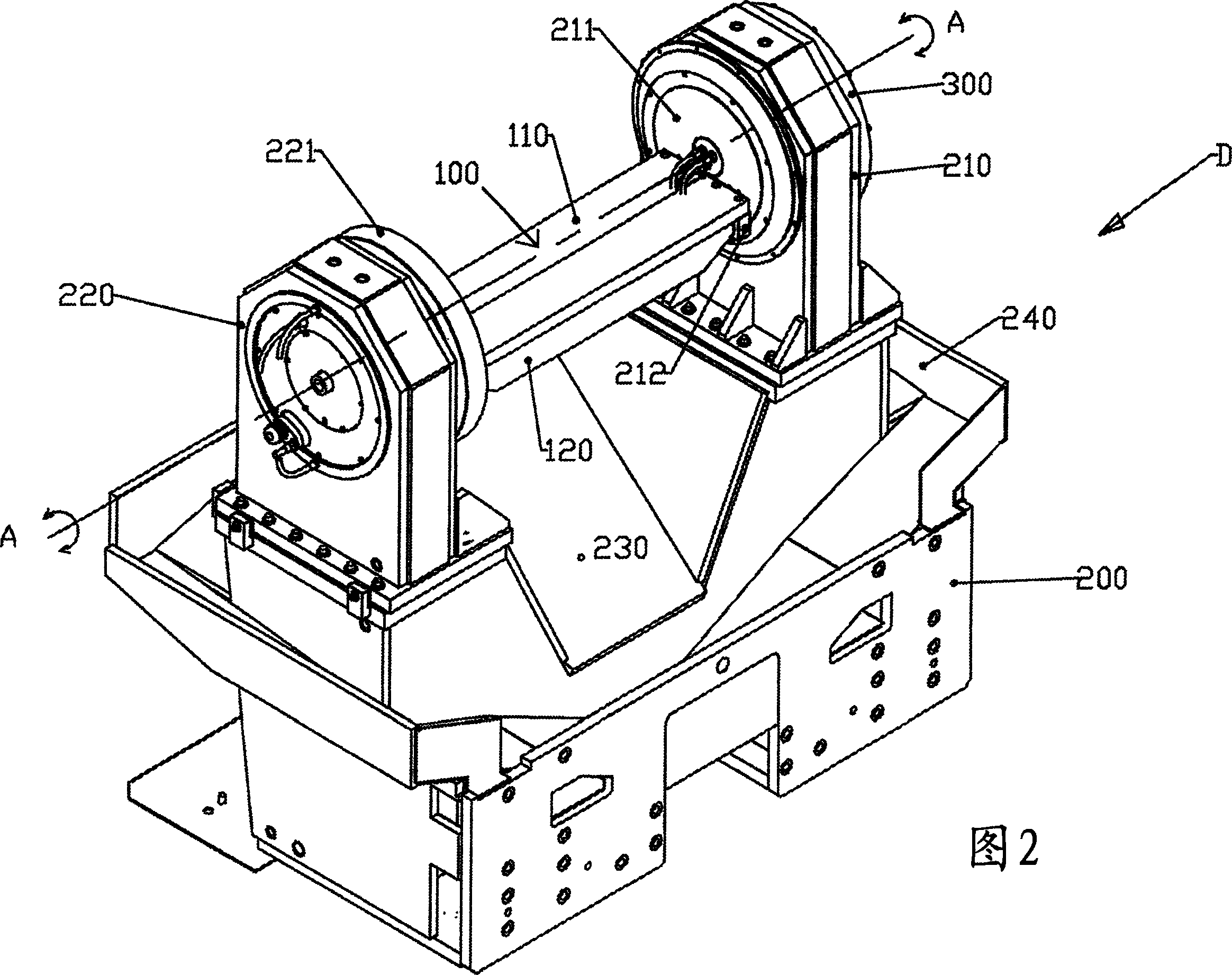
[0038]In order to better show the position of the device D relative to the processing tool, the rotatable table of the device has been removed, so that only the frame supporting the two bearings appears.

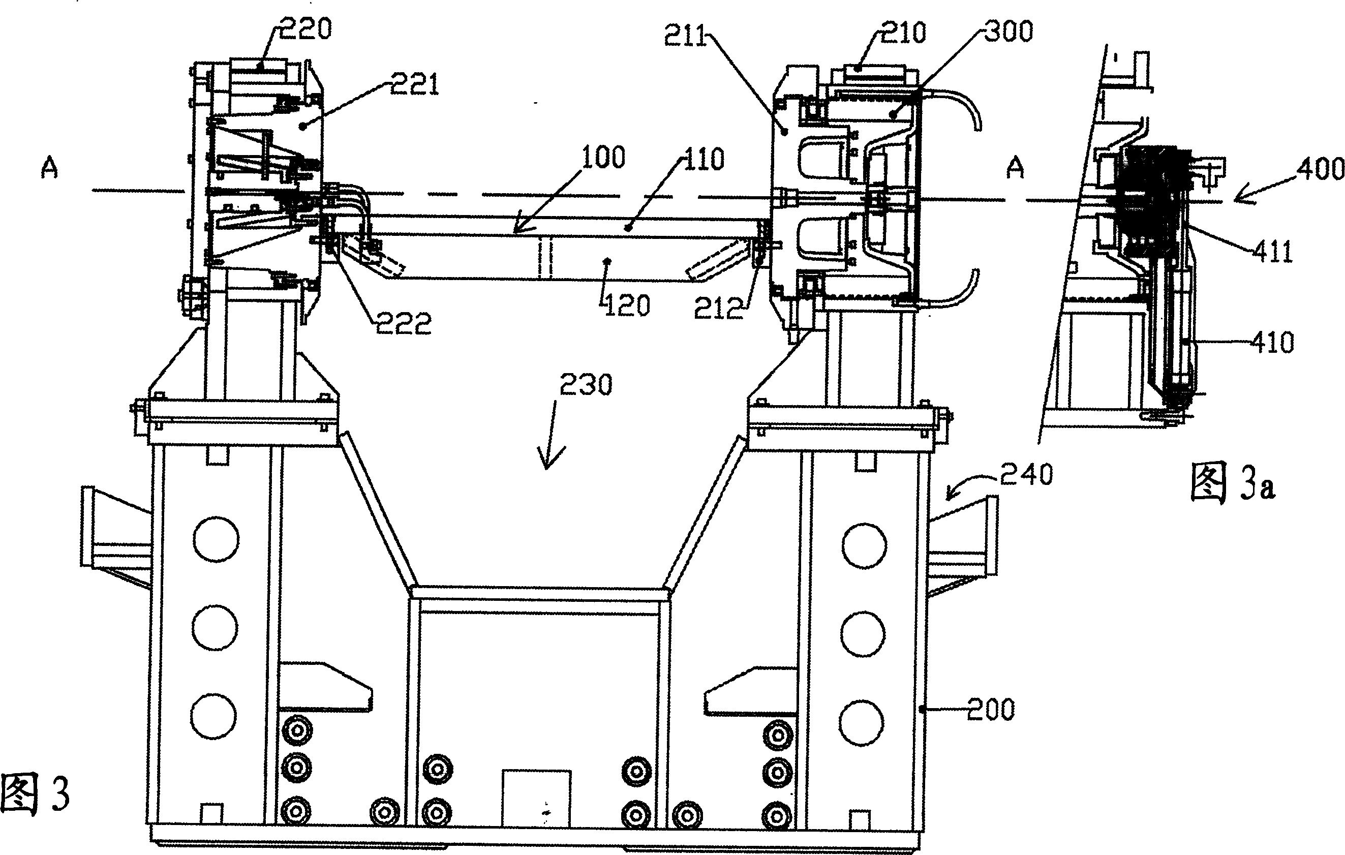
[0039] According to the invention, and as shown in Figures 2 and 3, the device D compr...


PUM


Abstract

The invention relates to a workpiece holding device (D), provided with a transversal rotation axis in relation to the tool downward axis of a machining machine tool (M), with which the device (D) is associated. Said device is characterised in being composed of a frame supporting two bearings for rotational guiding according to said transversal rotation axis, the structure formed by the frame and both bearings being closed by a rotary worktable, the ends of which are removably connected to both rotational guiding bearings which are arranged to take into account axial forces. Said device applies to workpiece holding inside a machining station.

Description

technical field [0001] The present invention relates to machine tools and, more particularly, to devices enabling the movement of workpieces to be produced in optimized conditions inside a machining station. Background technique [0002] Depending on the desired processing, the workpiece holding device of a processing station allows various possible movements of the workpiece between and during the different processing performed on it. These actuations make it impossible for the workpiece to be removed from or reloaded into its workpiece holding means in cases where the machining production schedule of the workpiece calls for one or more machining operations on different sides of the workpiece. [0003] In fact, the workpiece during machining is connected to a machining gantry to provide very precise position fixation and position maintenance. The operation of removing or reinstalling is not only tedious, but also risks creating repositioning defects. [0004] The tool its...

Claims


Application Information

Patent Timeline
Patent Type & Authority Applications(China)
IPC IPC(8): B23Q16/10B24B41/06B23Q1/52B23Q7/02B23Q11/00
CPCB23Q11/0021B23Q7/02B23Q1/52B23Q16/102Y10T409/305824B23Q16/10B24B41/06
Inventor 皮尔利·贝特里
Owner COMAU SYST FRANCE
Why Eureka
Try Eureka